The facelifted third-generation Ford Transit and Ford Tourneo , renowned for their durability and versatility, were produced from 2006 to 2014 . Designed to meet the demands of commercial and passenger transport, these models combined reliability, practicality, and efficiency, making them a popular choice for various applications.
In this article, you will find fuse box diagrams for Ford Transit and Ford Tourneo models produced between 2006 and 2014 , covering years 2006, 2007, 2008, 2009, 2010, 2011, 2012, 2013, and 2014 . These diagrams provide essential information about the fuse layout and relay assignments, helping owners and technicians maintain and troubleshoot the vehicle’s electrical systems effectively.
What’s Included:
Fuse Box Diagrams : Clear visuals for easy identification of fuses and relays.Fuse Panel Locations : Instructions on where to locate the fuse panels inside the vehicle.Fuse Assignments : Detailed explanations of each fuse and relay’s function for accurate diagnostics and repairs.
Whether you’re addressing an electrical issue, replacing a fuse, or conducting routine maintenance, this guide is an invaluable resource for Ford Transit and Ford Tourneo owners and technicians. It ensures your vehicle’s electrical systems remain reliable and functional.
Keep your Ford Transit and Ford Tourneo (2006–2014) running smoothly with this detailed fuse box guide!
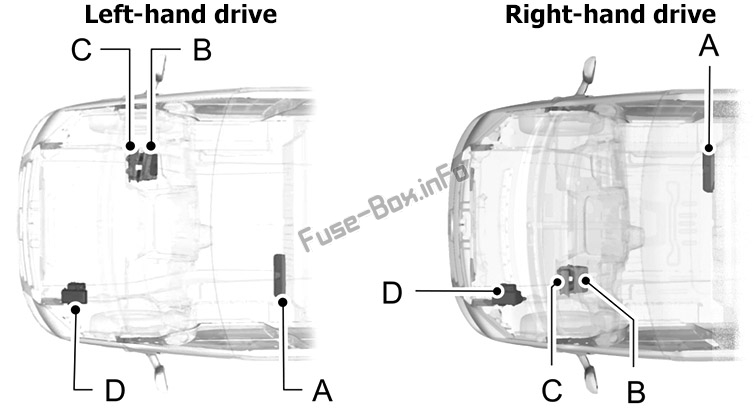
A – Pre-fuse box;B – Standard relay box;C – Passenger compartment junction box;D – Engine compartment junction box.
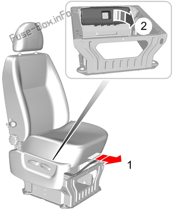
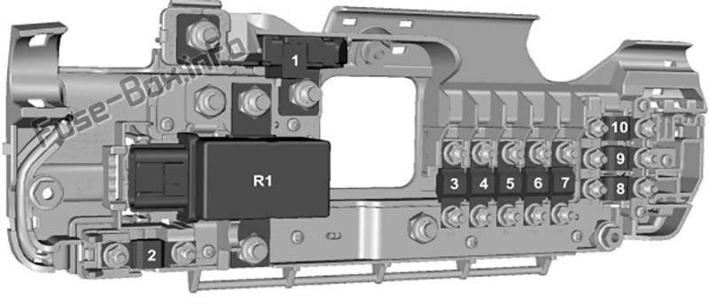
It is located under the driver’s seat.
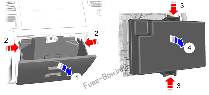
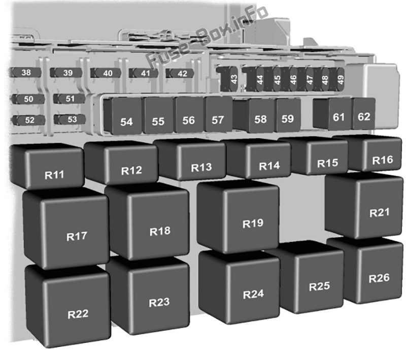
It is located behind the glove compartment.
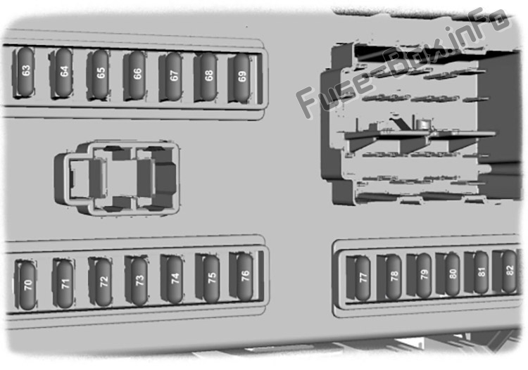
It is located behind the glove compartment.
Assignment of the fuses under seat (2006-2014)
№ Amp Description 1 350A Starter motor and alternator 2 60A Passenger junction box power supply – start relevant / Passenger junction box KL15 for Start-Stop 3 100A Engine junction box power supply – non-start relevant 4 40A Heated front screen right-hand side 5 100A Standard relay box power supply – non-start relevant 6 40A Heated front screen left-hand side 7 60A Passenger junction box power supply – non-start relevant 8 60A Customer connection point 9 60A Customer connection point 10 60A Customer connection point R1 Second battery disconnect switch relay
Login or Register to view this content
Assignment of the fuses in the Glove compartment (2006-2014)
№ Amp Description 38 20A Rear window wiper 39 10A Front and rear air conditioning control 40 5A Not used 41 5A Tachograph 42 5A Headlamp levelling, master light switch (KL15) 43 20A Heated front seats 44 20A Horn 45 20A Auxiliary power point front 46 10A Heated door mirrors, if CAT 1 fitted 47 20A Cigar lighter 48 5A Relay coils supply, power mirrors 49 20A Auxiliary power point rear 50 10A Main beam left-hand side 51 10A Main beam right-hand side 52 10A Dipped beam left-hand side 53 10A Dipped beam right-hand side 54 30A Pre-fuse for dipped beam, main beam, daytime running lamps, tachograph, fuel-fired booster heater blower 55 40A Heater blower motor 56 20A Power windows 57 30A Rear heater blower motor 58 30A Front wiper motor 59 30A Heated rear window, heated door mirrors 60 – Not used 61 60A Ignition relay (KL15 #1) 62 60A Ignition relay (KL15 #2) Relays R11 Headlamp dip beam R12 Heated door mirrors (if CAT 1 alarm is fitted), power outlet (if CAT 1 alarm is not fitted) R13 Headlamp main beam R14 Horn R15 Daytime running lamps R16 Programmable fuel fired heater R17 Heated rear windows and heated door mirrors (or heated rear window left-hand side if Cat 1 alarm is fitted) R18 Heated rear window right-hand side if Cat 1 alarm is fitted R19 Power feed (KL15 #2) R20 PJB KL15 (Start-Stop only) R21 Power feed (KL15 #1) R22 Heated windscreen right-hand side R23 Windscreen wiper high and low function R24 Rear window wiper R25 Windscreen wiper on and off function R26 Heated windscreen left-hand side
Login or Register to view this content
Assignment of the fuses in the Passenger compartment (2006-2014)
№ Amp Description 63 5A Rear parking aid, rain sensor 64 2A Acceleration pedal demand sensor 65 15A Brake lamp switch 66 5A Instrument cluster, PATS supply, tachograph, instrument panel switch illumination 67 15A Washer pump 68 10A Restraints control module 69 20A Exterior lamp switch (KL15) 70 20A Battery backed sounder 71 5A Exterior lamp switch (KL30) 72 10A Battery saver supply, OBDII (KL30) 73 15A Radio, navigation unit and phone supply 74 5A Instrument cluster, fuel-fired booster heater timer, remote keyless entry supply, interior motion sensor (KL30) 75 7.5A Side lamps right-hand side 76 7.5A Side lamps left-hand side 77 5A Ignition switch supply, battery disconnect switch coils supply 78 15A Central locking 79 7.5A Number plate lamp, side markers 80 15A Front fog lamps 81 10A Rear fog lamps 82 3A Audio and instrument cluster ignition feed Auxiliary fuses 83 10A Trailer tow module (location – Left-hand side footwell) 84 7.5A DPF glow plug sensing (location – Below the engine compartment junction box )
Login or Register to view this content
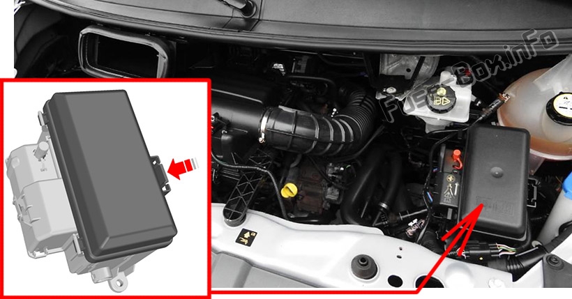
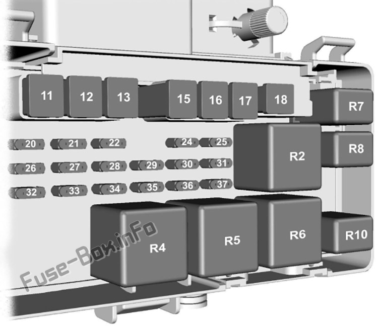
Assignment of the fuses in the Engine compartment (2006-2014)
№ Amp Description 11 60A Engine cooling fan 12 30A Trailer tow and trailer tow module power supply (KL30) 13 40A ABS and ESP pump 14 – Not used 15 60A Glow plugs 16 60A Ignition relay (KL15 #3) 17 30A Starter enable 18 40A Ignition feed (KL15) to Passenger junction box (vehicles without Start-Stop) 18 – Not used (vehicles with Start-Stop) 19 – Not used 20 10A ABS, ESP, steering angle sensor, YAW sensor supply (KL30) 21 25A ABS and ESP valves and control unit 22 – Not used 23 – Not used 24 5A Fuel pump (without fuel-fired heater) 24 20A Fuel pump (with fuel-fired heater) 25 – Not used 26 15A PCM Power 27 5A Fuel pump (with fuel-fired heater) 28 5A T-MAF sensor 29 5A Vaporiser glow plug monitoring 30 7.5A Sonic purge valve 31 15A VAP pump/UEGO 32 20A Vaporiser glow plug 33 10A Reversing lamps 34 20A Trailer KL15 Power supply 35 – Not used 36 10A Air conditioning clutch 37 – Not used Relays R2 Glow plugs R3 Trailer tow (KL15) R4 Starter enable R5 Power feed (KL15 #4) R6 Power feed (KL15 #3) R7 Fuel pump R8 Vaporiser glow plug R9 Not used R10 Air conditioning clutch solenoid
Login or Register to view this content