Mercedes-Benz C-Class Fuse Box Locations and Diagrams (2000-2007)
The second-generation Mercedes-Benz C-Class (W203), produced from 2000 to 2007, is a refined compact executive car that elevated the brand’s appeal in the entry-luxury segment. Offering a balance of performance, comfort, and style, the W203 was available in sedan, wagon, and coupe body styles, and featured a wide range of petrol and diesel engines. Its solid build quality, advanced safety systems, and sophisticated design make it a lasting favorite among enthusiasts and daily drivers alike.
In this article, you will find fuse box diagrams for the Mercedes-Benz C-Class, covering models C160, C180, C200, C220, C230, C240, C270, C280, C320, C350, C30 AMG, C32 AMG, and C50 AMG for the years 2000, 2001, 2002, 2003, 2004, 2005, 2006, and 2007. These diagrams provide vital information about the fuse layout, helping owners and technicians identify and troubleshoot electrical components and relays.
What’s Included:
Fuse Box Diagrams – Clear and detailed visual diagrams showing the location and designation of each fuse and relay.
Fuse Panel Locations – Guidance on where to locate fuse panels within the vehicle for quick access.
Fuse Assignments – Accurate descriptions of each fuse’s purpose to support electrical diagnostics and maintenance.
Whether you’re fixing a non-functional accessory, tracking down a blown fuse, or conducting preventative maintenance, this comprehensive guide is an invaluable tool for maintaining the reliability and electrical performance of your Mercedes-Benz C-Class (W203).
Keep your vehicle operating smoothly with this essential fuse panel, fuse layout, and relay identification resource!
The cigar lighter (power outlet) fuses in the Mercedes-Benz C-Class are:
Fuse №47: Front Cigar Lighter (located in the Engine Compartment Fuse Box)
Fuse №12: Interior Socket / Power Outlet (located in the Luggage Compartment Fuse Box)
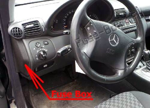
The fuse box is located on the driver’s side edge of the instrument panel, behind the cover.
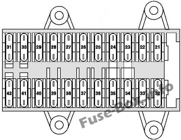
Fuse box diagram
Assignment of the fuses in the instrument panel
№
Circuit protected
Amp
21
Left front door control unit
30
22
Right front door control unit
30
23
Up to 30.11.04: Central gateway control unit
15
24
CD player with changer (in glove compartment)
7.5
25
Upper control panel control unit
30
26
Sound amplifier
25
27
Driver-side front seat adjustment control unit, with memory Special vehicle multifunction control unit (SVMCU [MSS])
30
28
Spare
30
29
Driver-side front seat adjustment control unit, with memory Driver-side front seat adjustment control unit, with memory Special vehicle multifunction control unit
30
30
Heating systems recirculation unit
40
31
EIS [EZS] control unit Electric steering lock control unit
20
32
Left rear door control unit
30
33
Right rear door control unit
30
34
Cell phone separation point up to 31.5.01: Telephone and TELE AID transmitter/receiver, D2B Telephone transmitter and receiver unit, D2B Telephone interface E-net compensator up to 31.5.01, Japan version: E-call control unit
7.5
34
up to 31.3.04: Front passenger front seat adjustment control unit with memory as of 1.4.04: Passenger-side front seat adjustment control unit with memory up to 31.5.03, Taxi: Special vehicle multifunction control unit as of 1.6.03, Taxi: Special vehicle multifunction control unit as of 1.6.01, Police: Special vehicle multifunction control unit
15
34
as of 1.4.04: Front passenger front seat adjustment control unit with memory as of 1.4.04, Taxi: Special vehicle multifunction control unit
30
35
up to 31.3.04 : STH heater unit
30
35
as of 1.4.04 : STH heater unit
20
36
up to 31.3.04, Police: Interior socket
30
36
Valid for engine (612.990) (up to 29.2.04): Charge air cooler circulation pump as of 1.4.04, Japan version: Audio gateway control unit
15
36
Universal Portable CTEL Interface (UPCI [UHI]) control unit
7.5
37
Charge air cooler circulation pump up to 29.2.04: Brake booster vacuum pump control unit
25
38
up to 29.2.04:Passenger-side front seat adjustment control unit with memory as of 1.4.04, Police:Special vehicle multifunction control unit (SVMCU [MSS])
30
39
Spare
30
40
Passenger-side front seat adjustment control unit with memory Universal Portable CTEL Interface (UPCI [UHI]) control unit Cell phone separation point Telephone interface E-net compensator as of 1.6.01, MB standard telephone: Telephone transmitter and receiver unit, D2B as of 1.6.01, TELE AID: Telephone and TELE AID transmitter/receiver, D2B as of 1.6.01, Canadian vehicles: Via the trunk lid/FFS [RBA] separation point the trunk lid emergency release switch and the rear SAM control unit with fuse and relay module USA version: Via the trunk lid/FFS [RBA] separation point the trunk lid emergency release switch and the rear SAM control unit with fuse and relay module as of 1.4.04, Japan version: E-call control unit
7.5
40
up to 31.5.01: Special vehicle multifunction control unit
30
41
HEAT control and operating unit up to 31.5.01: AAC [KLA] control and operating unit Comfort AAC [kLa] control and operating unit
7.5
41
as of 1.6.01: AAC [KLA] control and operating unit Comfort AAC [KLA] control and operating unit
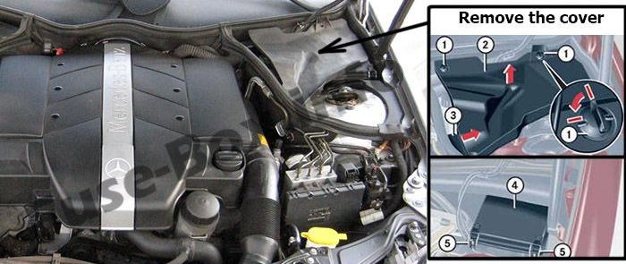
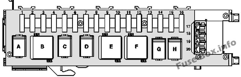
The fuse box is located in the engine compartment (left-side), under the cover.
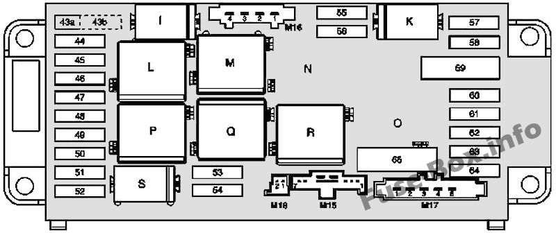
Fuse box diagram
Assignment of the fuses and relay in the engine compartment
№
Circuit protected
Amp
43a
Fanfare horn relay
15
43b
Fanfare horn relay
15
44
Telephone and TELE AID transmitter/ receiver, D2B Telephone transmitter and receiver unit, D2B Cell phone separation point
5
45
Restraint systems control unit
7.5
46
Wiper ON/OFF relay Wiper speed 1 and 2 relay
40
47
Glove compartment illumination with switch Front cigar lighter (with illumination)
15
48
Valid for engine 612.990 (up to 31.3.04): Brake booster vacuum pump control unit Valid for engine 112 and engine 113: Circuit 15 connector sleeve (fused) Valid for engine 646, USA version (up to 31.3.04): Circuit 30 connector sleeve Valid for engine 646 (as of 1.4.04): O 2 sensor upstream of TWC [kAt] connector
15
49
Restraint systems control unit
7.5
50
Light switch module Valid for engine 612.990: Glow output stage (up to 31.3.04), Hot film mass air flow sensor (1.4.04 up to 30.11.04)
5
51
AAC with integrated control additional fan motor Instrument cluster Valid for code (581) comfort automatic air conditioning: C-AAC [K-KLA] multifunction sensor, C-AAC [K-KLA] sun sensor (4 in total), Left front lamp unit, Right front lamp unit Valid for AMG vehicles: Charge air cooler circulation pump Valid for model 203.0 (up to 31.7.01): SPS [PML] control unit
7.5
52
Starter
15
53
Starter relay Rear SAM control unit with fuse and relay module Valid for engine 611/612/642/646: CDI control unit
25
53
Valid for gasoline engines: Starter relay Rear SAM control unit with fuse and relay module Valid for engine 111/271/272: ME-SFI [ME] control unit Valid for engine 112/113: ME-SFI [ME] control unit Circuit 87M1e connector sleeve
15
54
Valid for engine 271.940: ME-SFI [ME] control unit Purge control valve (USA version) Activated charcoal canister shutoff valve Valid for engine 271.942: NOX (nitrogen oxides) control unit Valid for engine 642/646: CDI control unit Valid for engine 642/646: Circuit 30 connector sleeve
15
54
Valid for engines 611/612: CDI control unit Valid for engine 611/612 (up to 30.11.04): Vent line heater element
7.5
55
Steering angle sensor Distronic: DTR control unit Valid for transmission 722: ETC [EGS] control unit (up to 31.5.04) Electronic selector lever module control unit Electric controller unit (VGS) Valid for transmission 716: Gear recognition switch Automated manual transmission control unit
7.5
56
ESP and BAS control unit Stop light switch
5
57
Steering angle sensor (up to 31.5.02) EIS [EZS] control unit Steering column module (as of 1.6.02) Valid for engine 112/113: ME-SFI [ME] control unit
5
58
Valid for transmission 716: SEQ hydraulic pump
40
59
ESP and BAS control unit
50
60
ESP and BAS control unit
40
61
Valid for transmission 716: Automated manual transmission control unit
15
62
Data link connector Light switch module Stop light switch
5
63
Light switch module
5
64
Radio Radio and navigation unit COMAND operating, display and control unit
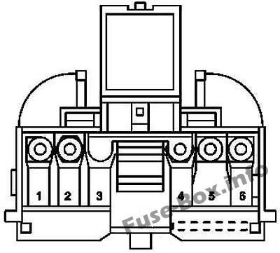
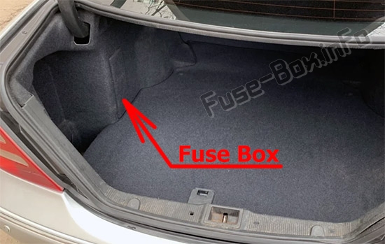
The fuse box is located in the luggage compartment (on the left-side), behind the cover.
Fuse box diagram
Assignment of the fuses and relay in the trunk
№
Circuit protected
Amp
1
Front passenger front seat adjustment control unit with memory Front passenger partially-electric seat adjustment switch
30
2
Driver front seat adjustment control unit with memory Driver partially-electric seat adjustment switch
30
3
Dome lamp Right luggage compartment lamp Left luggage compartment lamp STH radio remote control receiver
7.5
3
TV tuner (up to 29.2.04) TV tuner (MOST) (as of 1.4.04)
20
4
Fuel pump relay (N10/2kA)
20
5
Valid for engine 112.961 (up to 31.3.04): Charge air cooler circulation pump
Valid without engine 112.961: Backup relay 2
20
6
Spare
25
7
Backup relay 1
7.5
8
Amplifier module, window antenna Alarm signal horn (H3) ATA [EDW] inclination sensor
7,5
9
Overhead control panel control unit
25
10
Heated rear window
40
11
Spare
20
12
Interior socket Valid for model 203.0 USA version (up to 31.3.04): Power outlet
15
13
Multicontour seat pneumatic pump Voice control system control unit Rear dome lamp Rear dome lamp PTS warning indicator PTS control unit Japan version: VICS+ETC voltage supply separation point.
5
14
Tailgate wiper motor
15
15
Fuel filler cap polarity change relay 1 Fuel filler cap polarity change relay 2
10
16
Voice control system control unit
20
17
Trailer recognition control unit
20
18
Trailer hitch socket (13-pin)
20
19
Multicontour seat pneumatic pump
20
20
Rear window roller blind relay Valid for model 203.2/7 USA version: Power outlet