Toyota Previa / Estima / Tarago (2000-2005)

The second-generation Toyota Previa (Model Codes: XR30/XR40) — also known as the Toyota Estima and Toyota Tarago in various markets — was produced from 2000 to 2005. This generation transitioned from the unique mid-engine layout of the original Previa to a more conventional front-engine, front-wheel-drive (or all-wheel-drive) design, improving interior space and serviceability while maintaining the vehicle’s reputation for reliability and practicality.

In this article, you will find fuse box diagrams for the Toyota Previa / Estima / Tarago, covering model years 2000, 2001, 2002, 2003, 2004, and 2005. These diagrams help identify the correct fuses and relays for diagnosing and maintaining your vehicle’s electrical systems.

What’s Included:

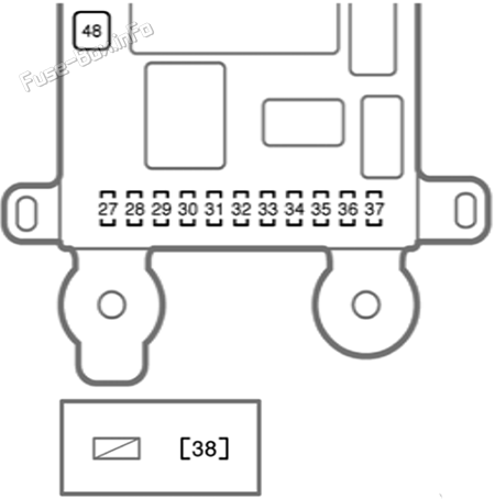
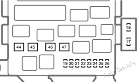
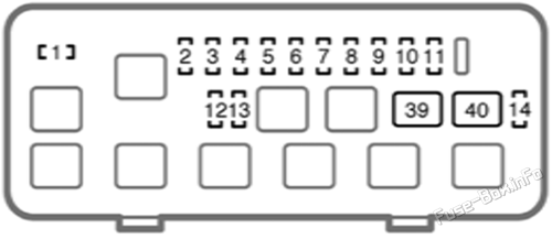
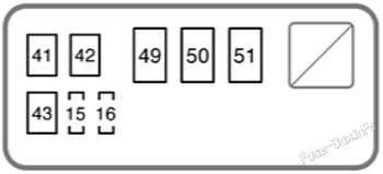
  • Fuse Box Diagrams – Visual representations showing the fuse layouts and relay locations.
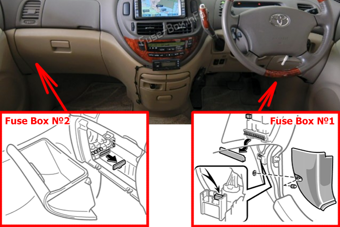
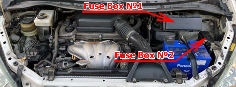
  • Fuse Panel Locations – Step-by-step guidance on where to locate the interior and engine compartment fuse boxes.
  • Fuse Assignments – Comprehensive listings of what each fuse and relay controls (e.g., headlights, horn, A/C, power windows, radio).

Whether you’re replacing a blown fuse or troubleshooting an electrical problem, this guide will assist you in keeping your Toyota Previa / Estima / Tarago (2000–2005) running smoothly and reliably.

Passenger Compartment

Fuse Box Location

Location of the fuses in the passenger compartment: Toyota Tarago / Previa (2003-2005)

Fuse Box Diagrams

Fuse Box №1

Interior fuse box #1 diagram: Toyota Tarago / Previa (2003-2005)

Assignment of the fuses in the Fuse Box №1 (driver’s side)

NameAmpDescription
27STOP15AStoplights, high mounted stoplight
28GAUGE10AGauges and meters, air conditioning system, service reminder indicators
29A/C7.5AAir conditioning system
30S-HTR (R)10ASeat heater (right)
31S-HTR (L)10ASeat heater (left)
32IGN15AGauges and meters, changing system, SRS airbag system, multiport fuel injection system / sequential multiport fuel injection system
33ECU-IG15ARear window defogger, anti-lock brake system, power windows multiport fuel injection system / sequential multiport fuel injection system
34WIP30AWindshield wipers and washer, rear window wiper and washer
35RR DOOR30ANo circuit
36AM17.5AStarter system
37OBD II7.5AOn-board diagnosis system
38MET7.5AGauges and meters
48RR HTR30AHeater system, gauges and meters

Login or Register to view this content

Fuse Box №2

Interior fuse box #2 diagram: Toyota Tarago / Previa (2003-2005)

Assignment of the fuses in the Fuse Box №2 (passenger’s side)

NameAmpDescription
17P/OUTLET15APower outlet
18CIG15ACar audio system, cigarette lighter, power rear view mirrors
19DOOR (RL)30ANo circuit
20RR FOG7.5ANo circuit
21FOG15AFront fog lights
22TAIL15ATail lights, license plate lights, instrument panel lights
23DEF20ARear window defogger, outside rear view mirror heaters, multiport fuel injection system / sequential multiport fuel injection system and “l/UP” fuse
24ACC30A“P/OUTLET” and “CIG” fuses
25T/M10ABack-up lights, clock
26l/UP10ARear window defogger, outside rear view mirror heaters, multiport fuel injection system / sequential multiport fuel injection system
44FR HTR40AHeater system and “BLC” fuse
45PWR30APower windows, electric moon roof
46DR LCK30APower door lock system
47VSC40ANo circuit

Login or Register to view this content

Engine Compartment

Fuse Box Location

Location of the fuses in the engine compartment: Toyota Tarago / Previa (2003-2005)

Fuse Box Diagrams

Fuse Box №1

Under-hood fuse box #1 diagram: Toyota Tarago / Previa (2003-2005)

Assignment of the fuses in the Fuse Box №1

NameAmpDescription
1SLC10ANo circuit
2H-LP (RH)15ARight-hand headlight (hiqh beam)
3H-LP (LH)15ALeft-hand headlight (high beam)
4H-LP (RL)15ARight-hand headlight and headlight beam level control
5H-LP (LL)15ALeft-hand headlight
6DOME10AClock, personal light, door courtesy lights
7HAZ-HORN20AEmergency flashers, turn signal lights, horn
8STA7.5AEngine starter system, multiport fuel injection system / sequential multiport fuel injection system
9EFI15AMultiport fuel injection system / sequential multiport fuel injection system
10RAD №115ACar audio system
11ECU-B10AService reminder indicators, air conditioning system
12SPARE15ASpare fuse
13SPARE7.5ASpare fuse
14ETCS10AElectronic throttle control system
39FAN-230AElectric cooling fans
40FAN-130AElectric cooling fans

Login or Register to view this content

Fuse Box №2

Under-hood fuse box #2 diagram: Toyota Tarago / Previa (2003-2005)

Assignment of the fuses in the Fuse Box №2

NameAmpDescription
15ABS25AAnti-lock brake system
16ALT-S5ACharging system
41FR DEF50ANo circuit
42ABS40AAnti-lock brake system
43AM2-230A“IGN”, “STA” and “MET” fuses
49AM280A“HAZ-HORN”, “RAD №1”, “ECU-B”, “EFI”, “H-LP (RH)”, “H-LP (LH)”, “H-LP (RL)”, “H-LP (LL)” and “DOME” fuses
50ALT140A“FR HTR”, “PWR”, “P/OUTLET”, “T/M”, “DEF”, “FOG”, “DOOR (RL)”, “DR LCK”, “TAIL”, “PTC1”, “PTC2”, “PTC3”, “AM1”, “VSC” and “RR FOG” fuses
51AM-1100A“A/C”, “GAUGE”, “ECU-IG”, “WIP”, “S-HTR (R)”, “S-HTR (L)”, “RR HTR”, “AM1 “, “RR DOOR”, “FAN-1”, “FAN-2”, “STOP” and “OBD II” fuses

Login or Register to view this content
Scroll to Top