The first-generation Volvo XC60, produced from 2008 to 2012, established itself as a premium compact SUV known for its elegant design, safety innovations, and Scandinavian engineering. Before its mid-cycle facelift in 2013, this model featured a clean aesthetic and a wide range of drivetrain options, appealing to both families and urban drivers.
In this article, you will find fuse box diagrams for the Volvo XC60, covering model years 2008, 2009, 2010, 2011 and 2012. These diagrams help identify fuses and relays responsible for various electrical systems, supporting quick and efficient troubleshooting.
What’s Included:
Fuse Box Diagrams – Detailed visuals of fuse and relay layouts for each applicable year.
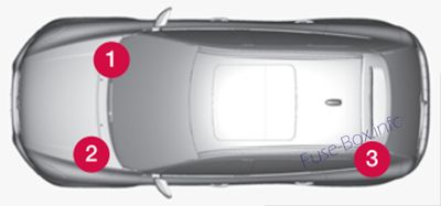
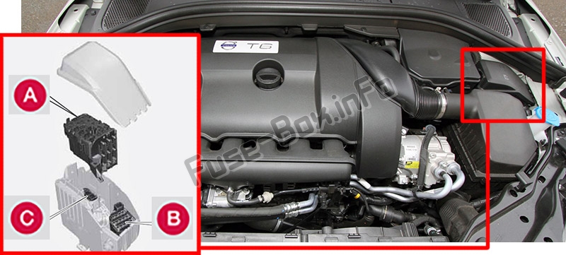
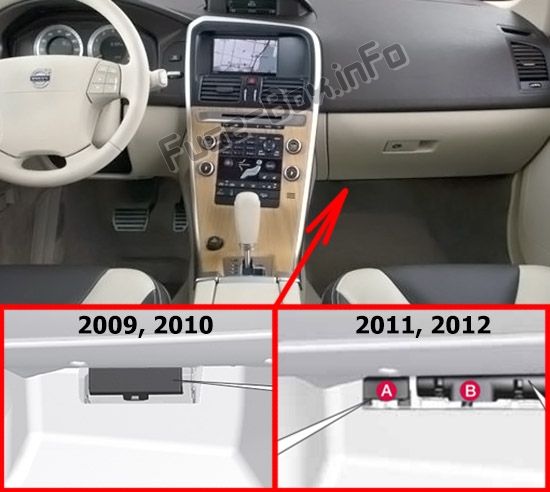
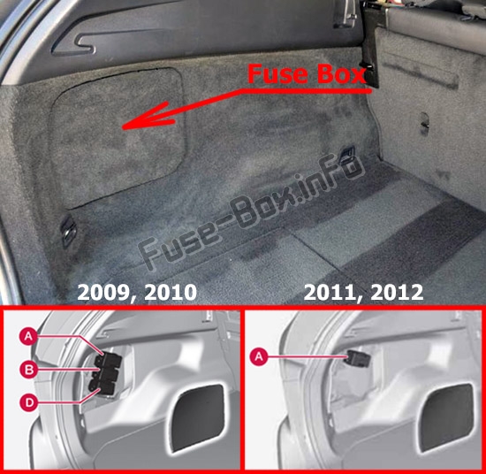
Fuse Panel Locations – Exact positions of fuse boxes inside the vehicle (e.g., under the hood, behind the glove box, or in the trunk).
Fuse Assignments – A comprehensive list describing what each fuse and relay controls.
Whether you’re repairing a non-functioning accessory or investigating a warning light, this guide will assist in maintaining your Volvo XC60 (2008–2012) with accuracy and confidence.
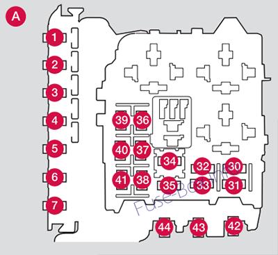
Fuses 16 – 33 and 35 – 41 may be changed at any time when necessary. Fuses 1 – 15, 34 and 42 – 44 are relays/ circuit breakers and should only be removed or replaced by a trained and qualified Volvo service technician.
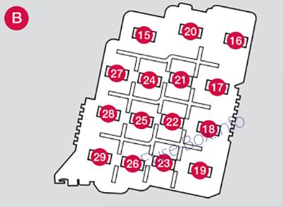
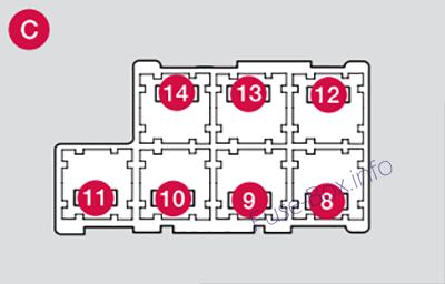
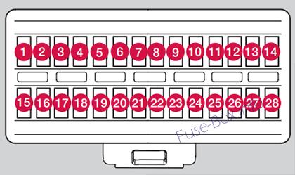
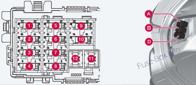
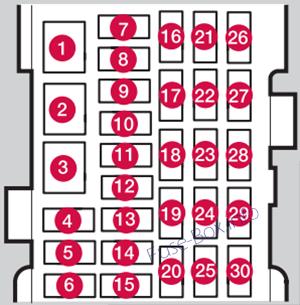
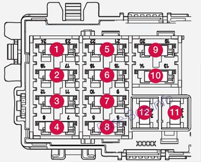
Under the glove compartment
Assignment of fuses under the glove compartment (2008, 2009, 2010)
№
Function
Amp
1
Rain sensor (option)
5
2
SRS system
10
3
ABS brakes. Electric parking brake
5
4
Accelerator pedal, heated seats (option)
7.5
5
–
6
ICM display, CD & Radio
15
7
Steering wheel module
7.5
8
–
9
High beam
15
10
Moonroof (option)
20
11
Backup lights
7.5
12
–
13
Front fog light (option)
15
14
Windshield washers
15
15
Adaptive cruise control ACC (option)
10
16
17
Overhead courtesy lighting, Control panel driver’s door/ Power passenger seat (option)
Fuses 16 – 33 and 35 – 41 may be changed at any time when necessary. Fuses 1 – 15, 34 and 42 – 44 are relays/ circuit breakers and should only be removed or replaced by a trained and qualified Volvo service technician.
Under the glove compartment (Fusebox A)
Assignment of fuses under the glove compartment (Fusebox A – 2011)
Fuses 16 – 33 and 35 – 41 may be changed at any time when necessary. Fuses 1 – 15, 34 and 42 – 44 are relays/ circuit breakers and should only be removed or replaced by a trained and qualified Volvo service technician.
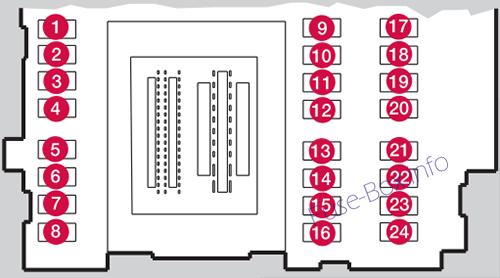
Under the glove compartment (Fusebox A)
Assignment of fuses under the glove compartment (Fusebox A – 2012)
№
Function
Amp
1
Circuit breaker for the infotainment system and for fuses 16-20
40
2
3
4
5
6
7
12-volt socket (cargo area)
15
8
Controls in driver’s door
20
9
Controls in front passenger’s door
20
10
Controls in right rear passenger’s door
20
11
Controls in left rear passenger’s door
20
12
Keyless drive (option)
20
13
Power driver’s seat (option)
20
14
Power front passenger’s seat (option)
20
15
Folding rear seat head restraints (option)
15
16
Infotainment system, Sirius satellite radio (option)
5
17
Audio system, Navigation system display (option)
10
18
Infotainment system
15
19
Bluetooth hands-free system
5
20
Rear Seat Entertainment system (RSE) (option)
7.5
21
Laminated panoramic roof (option); Courtesy lighting; Climate system sensor
5
22
12-volt sockets
15
23
Heated rear seat (passenger’s side) (option)
15
24
Heated rear seat (driver’s side) (option)
15
25
–
26
Heated front passenger’s seat (option)
15
27
Heated driver’s seat (option)
15
28
Park assist (option), Volvo Navigation System (option), Park assist camera (option)