The third-generation (Mk3) Audi A4 and S4 (chassis codes B7/8E/8H), Audi’s luxury sedan and high-performance variant, was produced from 2004 to 2008. Known for its sleek design, enhanced technology, and dynamic driving experience, this generation of the A4 and S4 further established Audi as a leader in the luxury sedan market.
In this article, you will find detailed fuse box diagrams for Audi A4 and S4 models produced in 2004, 2005, 2006, 2007 and 2008. These diagrams provide valuable insights into the vehicle’s electrical systems, helping owners and technicians understand the assignment of each fuse (fuse layout). This information is vital for diagnosing electrical issues, performing maintenance, or completing necessary repairs.
This guide serves as a comprehensive resource for understanding the electrical system of the third-generation Audi A4 and S4, ensuring that owners have the knowledge and tools needed to maintain the reliability, functionality, and performance of these premium sedans.
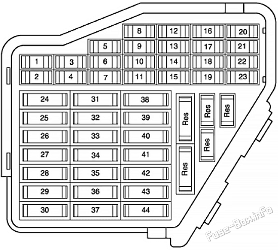
Left Washer Nozzle Heater Right Washer Nozzle Heater Left Rear Footwell Light Right Rear Footwell Light
4
5A
Coolant Fan Control (FC) Control Module Coolant Fan Control (FC) Control Module 2
5
10A
Rear Window Shade Switch Function Selector Switch II Tiptronic Switch Oil Level Thermal Sensor Rear Window Shade Control Module Navigation System with CD Drive Control Module Parking Aid Control Module
6
5A
High Pressure Sensor Sensor for air quality
7
10A
Anti-Slip Control Switch Clutch Pedal Switch Brake Pedal Switch ABS Control Module
8
5A
Telephone Transceiver Telephone Amplifier
9
15A
Brake Booster Relay
10
5A
Headlamp Adjuster Headlamp Range Control Module Headlamp Range/Comering Lamp Control Module Left Headlamp Beam Adjusting Motor Right Headlamp Beam Adjusting Motor Right Dynamic Cornering Light Motor
11
5A
Airbag Control Module Warning Lamp for airbag off, passenger side
12
10A
16 pin connector, black, diagnostic connector
13
10A
Steering Column Electronic Systems Control Module
14
10A
Brake Light Switch
15
10A
Instrument Cluster Control Module Navigation System with CD Drive Control Module
16
5A
Garage Door Opener Control Head Garage Door Opener Control Module
17
10A
Rain/Light Recognition Sensor Parking Aid Control Module Tire Pressure Monitoring Control Module
18
5A
Left Dynamic Cornering Light Motor
19
10A
Left Lront Fog Lamp Right Front Fog Lamp
20
–
Not used
21
–
Not used
22
15A
Drivers Door Control Module Front Passenger’s Door Control Module
23
15A
Left Rear Door Control Module Right Rear Door Control Module
24
20A
Comfort System Central Control Module
25
30A
Fresh Air Blower Control Module
26
30A
Rear Window Defogger Relay
27
30A
Towing Recognition Control Module
28
20A
Transfer Fuel Pump (FP) Fuel Pump (FP) Control Module
29
–
Not used
30
20A
Power Sunroof Control Module
31
15A
Back-Up Light Switch Mass Air Flow (MAF) Sensor Light Recognition Sensor Starting Interlock Relay Transmission Control Module (ICM)
32
15A
Trailer Socket
33
15A/20A
Cigarette lighter
34
20A/30A
12V Socket
35
20A/30A
Socket
36
30A
Vehicle Electrical System Control Module Rear Window Wiper Motor
37
30A
Vehicle Electrical System Control Module Headlamp Washer Pump
38
15A
Radar Interior Monitoring Control Module 1 Alarm Horn Comfort System Central Control Module 8 pin Connector, black, radio connector III
39
20A
Radio Amplifier
40
25A
High Tone Horn Low Tone Horn Horn Relay
41
30A
Auxiliary Heater Control Module Auxiliary Heater Radio Receiver
42
25A
ABS Control Module
43
15A
Engine Timing Mass Air Flow (MAF) Sensor EGR Potentiometer SIMOS Control Module Power Supply Relay Engine Control Module (ECM) Engine Component Power Supply Relay EGR Vacuum Regulator Solenoid Valve
44
30A
Climatronic Control Module
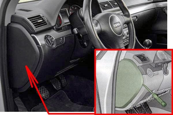
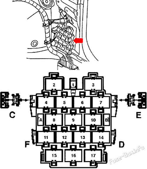
Connector station – Right A-pillar
Fuse Data
Full access is available to registered users — log in or register.
Brake Booster Relay (Not applicable for engine code AUK, BKH)
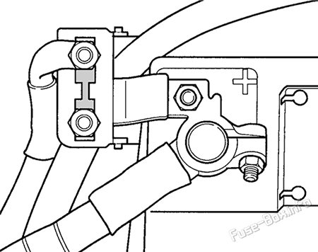
Main Fuse
The main fuse is located on the battery positive post, the fuse is numbered “S88” and has an amperage rating of 150 amps. The battery is located in the plenum chamber on right side of engine compartment.
 | 1995-2001 | Fuse Box Diagrams and Locations")
 | 2008-2015 | Fuse Box Diagrams and Locations")
 | 2015-2019 | Fuse Box Diagrams and Locations")
 | 2020-2025 | Fuse Box Diagrams and Locations")