The Audi e-tron GT , a battery-electric executive car , has been available from 2020 to the present . Combining cutting-edge electric vehicle technology, exceptional performance, and striking design, the e-tron GT stands as a flagship model in Audi’s transition to sustainable luxury mobility.
In this article, you will find detailed fuse box diagrams for Audi e-tron GT models produced in 2020, 2021, 2022, 2023, 2024 and 2025 . These diagrams provide critical insights into the vehicle’s electrical systems, helping owners and technicians understand the assignment of each fuse (fuse layout). This information is essential for diagnosing electrical issues, performing maintenance, or carrying out repairs efficiently.
This guide serves as a comprehensive resource for understanding the electrical system of the Audi e-tron GT, ensuring that owners have the knowledge and tools necessary to maintain the functionality, reliability, and performance of this innovative luxury electric vehicle.
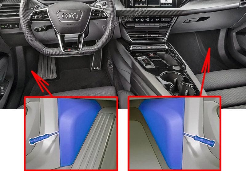
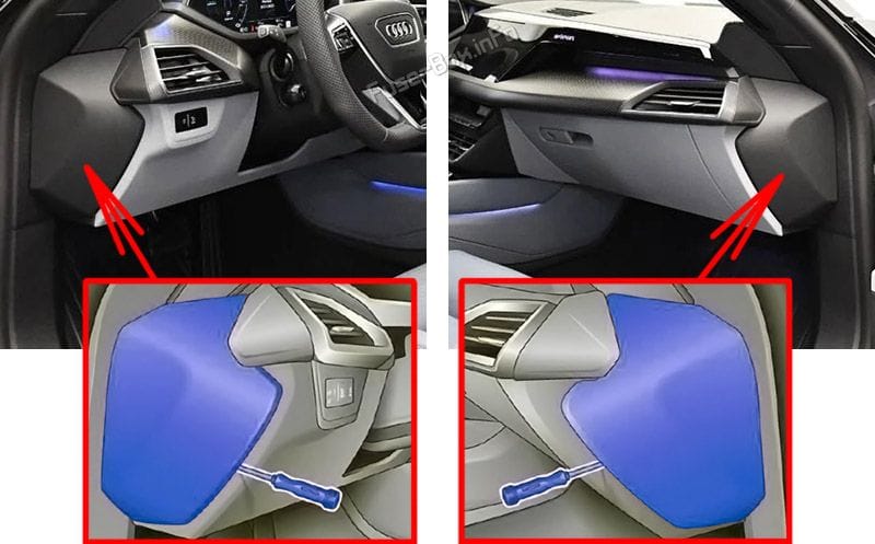
The fuses are located in the left and right footwells, as well as at the left and right front sides of the cockpit.
Fuse Data
Full access is available to registered users — log in or register.
Log in or register This content requires JavaScript and a valid membership to view.
Switch the ignition and all electrical equipment off.
Check the table that follows to see which fuse belongs to the affected equipment.
Use a screwdriver to remove the appropriate cover.
Remove the colored plastic bracket from the fuse panel, if present.
Remove the fuse.
Replace the blown fuse only with a fuse that has the same amp rating.
Reinstall the plastic bracket, if present.
Install the cover.
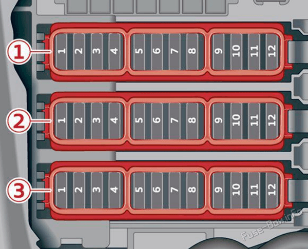
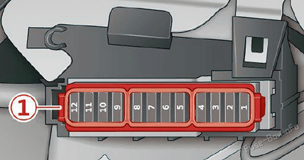
Left footwell fuse panel
Assignment of the fuses in the left footwell
Fuse Data
Full access is available to registered users — log in or register.
Log in or register
№ Equipment Fuse panel 1 (brown) 1 Heating circuit coolant pump 3 Thermal management 5 Vehicle electrical system control module 6 Vehicle electrical system control module 7 Light/rain/humidity sensor 8 Remote controlled parking 9 Roof electronics control module 10 Vehicle electrical system control module 12 Data exchange and telematics control module Fuse panel 2 (red) 1 Driver assistance systems control module 2 Left rear door control module 3 Thermal management 4 Windshield wipers 5 Electronic Stabilization Control (ESC) 7 Left front safety belt 8 Vehicle electrical system control module 9 Vehicle electrical system control module 10 Left headlight 11 Left front door control module 12 Vehicle electrical system control module Fuse panel 3 (white) 3 Vehicle electrical system control module 4 Diagnostic connection 6 Left front intersection assistant 7 Brake system pressure reservoir 8 Rearview mirror 9 Data exchange and telematics control module 10 Power supply 11 Power supply
This content requires JavaScript and a valid membership to view.
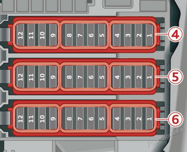
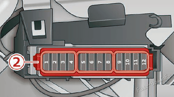
Right footwell fuse panel
Assignment of the fuses in the right footwell
Fuse Data
Full access is available to registered users — log in or register.
Log in or register
№ Equipment Fuse panel 4 (brown) 1 Vehicle electrical system control module 3 Vehicle electrical system control module 4 Windshield wipers 5 Vehicle electrical system control module 6 Right rear door control module 7 Driver assistance systems control module 8 Right front door control module 9 Airbag control module 10 Right front safety belt 11 Remote controlled parking 12 Vehicle electrical system control module Fuse panel 5 (red) 1 Diagnostic interface 3 Thermal management 4 Right headlight 5 Vehicle electrical system control module 6 Vehicle electrical system control module 7 Night vision assist control module 8 Driver assistance systems front camera 9 Rear climate control system control panel 11 Right front intersection assistant Fuse panel 6 (white) 1 Diagnostic connection 2 Diagnostic interface 3 Brake system pressure reservoir 4 Vehicle electrical system control module 5 Front power electronics control module 6 Ionizer 7 Power supply 8 Power supply 9 Voltage converter 10 Power steering 12 Adaptive cruise assist
This content requires JavaScript and a valid membership to view.
Assignment of the fuses in the left cockpit
Fuse Data
Full access is available to registered users — log in or register.
Log in or register
№ Equipment Fuse panel 1 (black) 1 Front climate control system control panel 2 Light switch 3 Climate control system control module 4 Head-up display control module 5 Steering column electronics 6 Steering column adjustment 8 Instrument cluster 11 Rear climate control system control panel 12 Steering column electronics, steering wheel heating
This content requires JavaScript and a valid membership to view.
Assignment of the fuses in the right cockpit
Fuse Data
Full access is available to registered users — log in or register.
Log in or register
№ Equipment Fuse panel 2 (brown) 1 Audi phone box 2 Infotainment system 3 Center display, volume control 4 Audi connect apps control module 5 Audi music interface 6 Climate control system blower 8 Selector lever positions 12 Diagnostic connection
This content requires JavaScript and a valid membership to view.