Access Cadillac Lyriq fuse box diagrams for 2023–2026 models with fuse locations, panel layouts, electrical system information, and detailed circuit assignments. This article covers the battery electric mid-size luxury crossover Cadillac Lyriq (also Cadillac Lyriq V), available from 2023, and includes fuse box diagrams for Cadillac Lyriq 2023, 2024, 2025 and 2026, along with details about the location of the fuse panels inside the vehicle and a clear explanation of the assignment of each fuse (fuse layout).
Lit Grille / Front Park Emblem and Semi Active Damping System
48
FMM/MCase
Power Tailgate
49
—
–
50
FMM/MCase
Motor Window Lifter Left
51
FMM/MCase
Suspension Control Leveling 1
52
FMM/MCase
Motor Window Lifter Right
53
FMM/MCase
Front Wiper
54
FMM/MCase
Trailer Battery
55
—
–
56
Micro2
Fold Seat Right Motor
57
FMM/MCase
Electronic Brake Control Module
58
FMM/MCase
Front Blower Motor
59
—
–
60
Micro2
Horn
61
FMM/MCase
Rear Defog
62
FMM/MCase
Rear Blower Motor
63
FMM/MCase
Motor Sunroof and Motor Sunshade
64
FMM/MCase
Power Seat Driver
65
FMM/MCase
Power Seat Passenger
66
FMM/MCase
Condenser Radiator Fan Module
67
FMM/MCase
Heated Wiper
68
Micro2
Spare
69
Micro3
Spare
70
Micro2
RELAY’S COIL
71
Micro2
Rear Heated Seat 2
72
Micro2
Front Heated Seat 1
73
Micro2
Fold Seat Left Motor
74
FMM/MCase
Trailer Interface Module Battery Source 2
75
Micro2
Spare
76
Micro2
Spare
77
Micro2
Spare
78
Micro3
Trailer Stop Turn Left and Trailer Stop Turn Right
79
Micro2
Rear Heated Seat 1
80
Micro2
Front Heated Seat 2
81
Micro2
Out of Park Disable
82
Micro2
Wash Pump (Front)
83
Micro2
Camera Wash
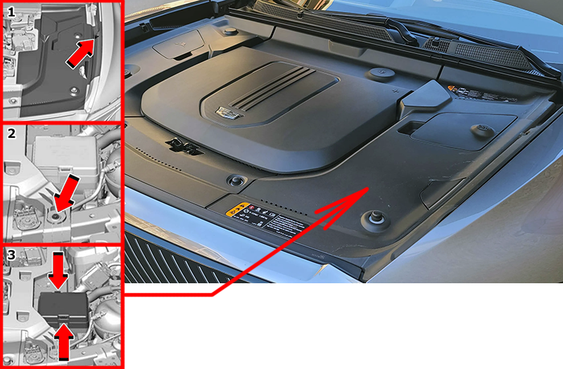
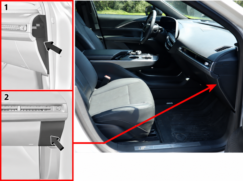
Passenger Compartment
Fuse Box Location
The instrument panel fuse block is located to the right of the glove box.
How to access the fuses:
To access the fuse panel, remove the trim panel starting from the top. After the retaining clips release, lift the panel away, allowing the lower tabs to disengage from the instrument panel.
To reinstall the panel, insert the lower tabs into their slots first, then rotate the panel back into position until the clips securely engage.
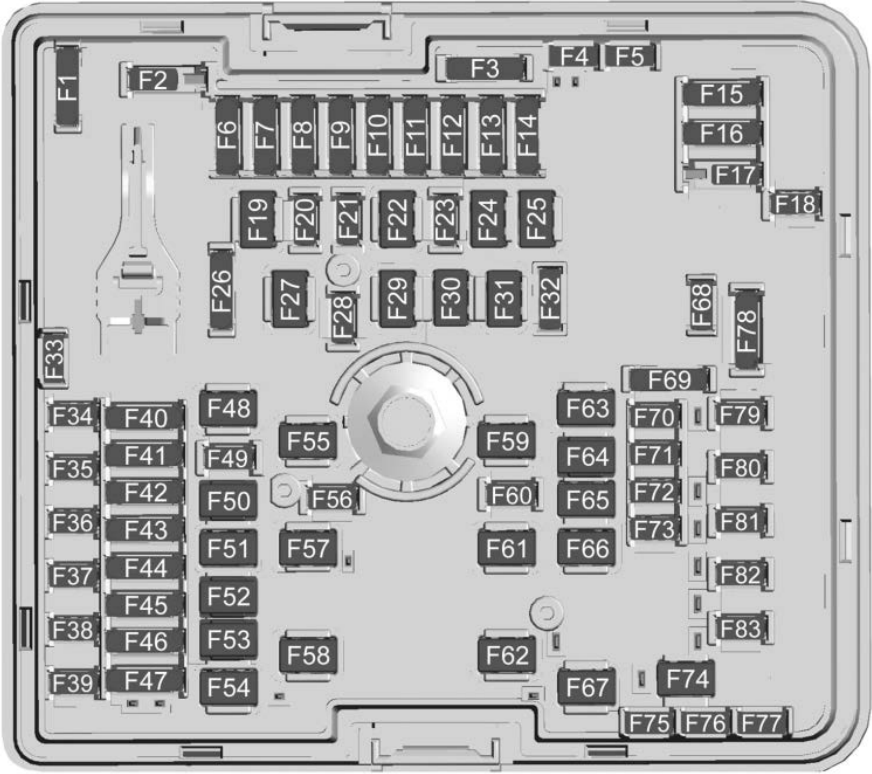
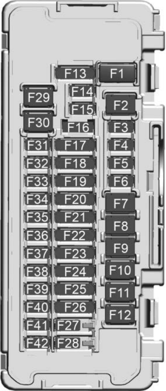
Fuse Box Diagram
Fuses
Assignment of the fuses in the passenger compartment
Fuse Data
Full access is available to registered users — log in or register.
Auxiliary Power Outlet Instrument Panel / Cigar Lighter
F3
—
–
F4
Micro2
Universal Serial Bus Port / Auxiliary Power Outlet Alternating Current 150W
F5
Micro2
Steering Column Lock
F6
Micro2
Exterior Lighting Module 1
F7
FMM/MCase
Amplifier (Base)
F8
FMM/MCase
Right Door Latch
F9
FMM/MCase
Left Door Latch
F10
FMM/MCase
Steering Column Position Module
F11
FMM/MCase
Compute Platform 4
F12
—
–
F13
Micro3
Trailer Control and Electrification Control Processor (Traction Power Inverter 1 and 2) / Vehicle Integration Control Module
F14
Micro2
Headlamps
F15
Micro2
Headlamp Right
F16
Mini
Steering Column Lock / Clock Spring
F17
Micro3
Seat Fan Passenger and Seat Fan Driver
F18
Micro3
Virtual Cockpit Display and Short Range Radar
F19
Micro3
Miscellaneous 2 Switch Bank / Electronic Toll Collection / lnterior Particulate Matter Sensor / Reflective Light Auxiliary Display and Miscellaneous 1 Electronic Brake Control Module / Exterior Lighting Module / Sensing and Diagnostic Module / lnside Rear View Mirror
F20
Micro3
Body Control Module 1 and Vehicle Integration Control Module
F21
Micro3
Long Range Radar – Rear and Electric Park Brake Switch / Electronic Transmission Range Select Shifter Module
F22
Micro3
2023: Virtual Key Module / Virtual Key Backup Module / Auxiliary Jack 2024-2026: Virtual Key Module/ Virtual Key Backup Module/ Auxiliary Jack and ADAS Compute Platform 3
F23
Micro3
Tail Lamp Right and Tail Lamp Left
F24
Micro3
Universal Park Assist / Automatic Park Assist / Side Blind Zone Alert and Sensing Diagnostic Module / Automatic Occupant Sensing Module
F25
Micro3
Compute Platform 2 / External Object Calculating Module / Front Camera Module / Multi Function Control and Driver Monitoring System / Central Gateway Module / Diagnostic Link Connector / Vehicle Data Monitor
F26
Micro3
Electrification Control Processor Battery 2 / Air Condition Electric Compressor and Heads-Up Display / Heating, Ventilation and Air Conditioning Display
F27
Micro2
Body Control Module 3
F28
Micro2
Body Control Module 2
F29
FMM/MCase
Amplifier (Uplevel)
F30
FMM/MCase
Body Control Module 4
F31
Micro2
Video Processing Module / SD Card / lndicator Light and Solar Sensor / Over Head Console
F32
Micro2
Heated Steering Wheel Module
F33
Micro2
Long Range Radar Front / Light Detection and Ranging