Explore Chevrolet Orlando fuse box diagrams in this helpful guide that outlines the electrical layout of this compact MPV. In this article, we consider the Chevrolet Orlando (Model Code: J309), produced from 2010 to 2018 , and provide fuse box diagrams for Chevrolet (Chevy) Orlando models from 2011, 2012, 2013, 2014, 2015, 2016, 2017 and 2018 , along with information about the location of the fuse panels and the assignment of each fuse and relay (fuse layout).
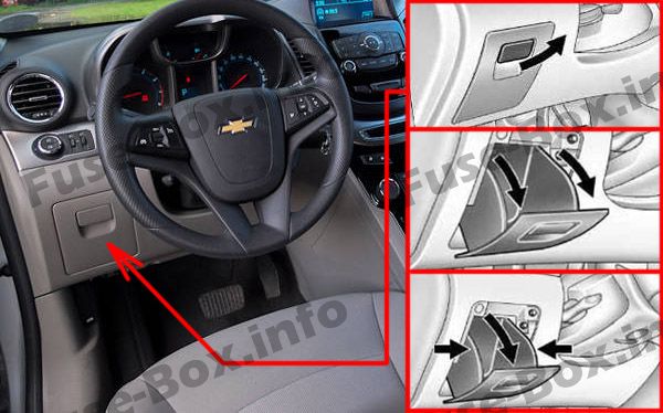
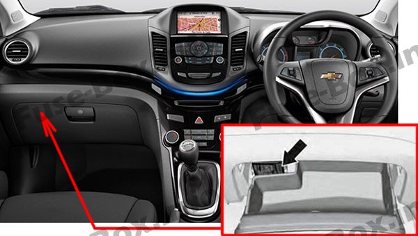
It is located in the instrument panel (on the left side), behind the cover (behind glovebox in RHD).
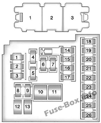
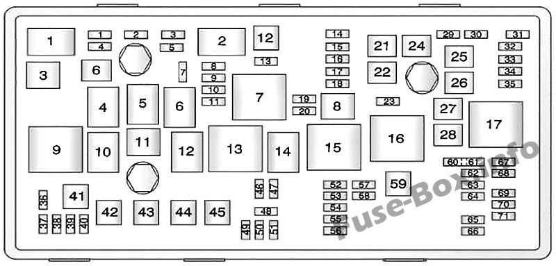
Assignment of the fuses and relay in the Instrument Panel
Fuse Data
Full access is available to registered users — log in or register.
Log in or register
No. Description Amps 1 Mobile Telephone Control Module 10 2 DC/DC Converter – 3 Body Control Module 25 4 Radio 20 5 Parking Assist Control Module, Power Sounder, Multifunction Switch – Centre Console, Display 7.5 6 Cigar Lighter 20 7 Power Outlet 20 8 Body Control Module 30 9 Body Control Module 30 10 Body Control Module 30 11 Blower Motor Control Module 40 12 Not Used – 13 Heated Seat Control Module 25 14 Data Link Connector, Oil Feeding Connector 7.5 15 Inflatable Restraint Sensing and Diagnostic Module 10 16 Rear Compartment Lid Release Relay 10 17 HVAC Control Module / HVAC Control Assembly 15 18 Trailer – 19 Battery Sensor – 20 Not Used – 21 Instrument Cluster 15 22 Ignition Switch 2 23 Body Control Module 20 24 Body Control Module 20 25 Not Used – 26 Auxiliary Power Outlet 20
This content requires JavaScript and a valid membership to view.
Non-serviceable relays (Printed Circuit Board (PCB)):
Fuse Data
Full access is available to registered users — log in or register.
Log in or register
No. Description 1 Tailgate Release Relay 2 Logistic Mode Relay 1 3 Auxiliary Power Relay
This content requires JavaScript and a valid membership to view.
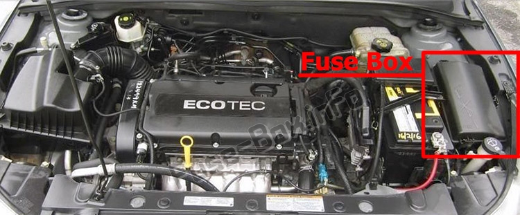
It is located in the engine compartment, under the cover.
Assignment of the fuses in the Engine Compartment
Fuse Data
Full access is available to registered users — log in or register.
Log in or register
No. Description Amps 1 Transmission Control Module 15 2 Engine Control Module 15 3 Not Used – 5 Transmission Control Module, Engine Control Module, Mass Air Flow/Intake Air Temperature Sensor, Output Speed Sensor 15 6 Windshield Wiper Relays 30 7 Not Used – 8 Fuel injectors 15 9 Ignition Coil, Fuel Injectors 15 10 Engine Control Module, Output Speed Sensor 15 11 Heated Oxygen Sensors 10 12 Starter Motor 30 13 Evaporative Emission (EVAP) Canister Vent Solenoid Valve 7.5 14 Not Used – 15 Rear Wiper 16 Air Quality Sensor 7.5 17 Inflatable Restraint Sensing and Diagnostic Module 5 18 Fuel Pump Control Module 10 19 Not Used – 20 Fuel Pump Relay 20 21 Windows Motors, Front Door 30 22 Not Used – 23 Not Used – 24 Windows Motors, Front Door 30 25 Electronic Vacuum Pump 26 Electronic Brake Control Module (EBCM) 40 27 Remote Control Door Lock Receiver 30 28 Rear Demister Grid 40 29 Not Used – 30 Electronic Brake Control Module (EBCM) 15 31 Body Control Module 20 32 Body Control Module 20 33 Heated Seat Control Module 30 34 Sunroof Control Module 25 35 Audio Amplifier 30 36 Not Used – 37 Headlamp – Right Main beam 10 38 Headlamp – Left Main beam 10 39 Not Used – 40 Not Used – 41 Not Used – 42 Cooling Fan Relays, Cooling Fan Motor 20/30 43 Not Used – 44 Not Used – 45 Cooling Fan High Speed Relay, Cooling Fan Motor 30/40 46 Cooling Fan Relays 10 47 Heated Oxygen Sensors, Throttle Body 10 48 Fog Lights, Front 15 49 Not Used – 50 Not Used – 51 Horn 15 52 Instrument Cluster 5 53 Inside Rearview Mirror 10 54 Headlamp Switch, Electrical Auxiliary Heater, HVAC Control Module 5 55 Window Switches, Front, Mirror Switch 7.5 56 Windscreen Washer Pump 15 57 Steering Column Lock Control Module 15 58 Not Used – 59 Fuel Heater 30 60 Outside Rearview Mirrors 7.5 61 Mirror Defogger 62 A/C Compressor Clutch Relay, A/C Compressor Clutch 10 63 Rear Window Sensor 64 Inflatable Restraint Sensing and Diagnostic Module 5 65 Rear Fog Lamp 66 Rear Washer 67 Fuel Pump Control Module 20 68 Not Used – 69 Body Control Module 5 70 Rain Sensor 5 71 Not Used –
This content requires JavaScript and a valid membership to view.
Assignment of the relay in the Engine Compartment
Fuse Data
Full access is available to registered users — log in or register.
Log in or register
No. Description 1 A/C Compressor Clutch 2 Starter 3 Cooling Fan 4 Windshield Wiper Speed Control 5 Windshield Wiper 6 Not Used 7 Powertrain 8 Fuel Pump 9 Cooling Fan Medium Speed 1 10 Cooling Fan Medium Speed 2 11 Not Used 12 Cooling Fan Speed Control (Or in Relay Block – Under-bonnet) 13 Cooling Fan High Speed Relay 14 Not Used 15 Ignition Main Relay 16 Fuel Heater Relay 17 Rear Window Defogger
This content requires JavaScript and a valid membership to view.
Fuse Data
Full access is available to registered users — log in or register.
Log in or register
Description Horn Relay Windscreen Washer Pump Relay Front Fog Lamp Relay Headlamp High Beam Relay
This content requires JavaScript and a valid membership to view.
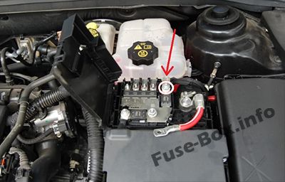
It is located on the battery terminal.
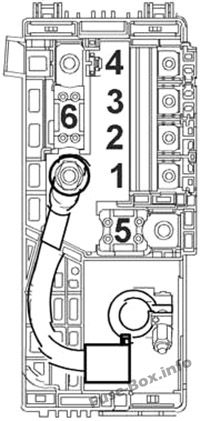
Engine Pre-Fuse Box No.1
Fuse Data
Full access is available to registered users — log in or register.
Log in or register
No. Description Amps 1 Fuse Block – Instrument Panel 100 2 Fuse Block – Instrument Panel 100 3 Electrical Power Steering (EPS) (NJ1) 80 4 Not Used – 5 Fuse Block – Battery Auxiliary 250 6 Starter Motor 250/500
This content requires JavaScript and a valid membership to view.
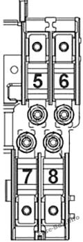
Engine Pre-Fuse Box No.2
Fuse Data
Full access is available to registered users — log in or register.
Log in or register
No. Description Amps 5 Glow Plug Control Module 80 6 Electrical Auxiliary Heater 100 7 Not Used – 8 Not Used –
This content requires JavaScript and a valid membership to view.
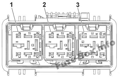
Assignment of the relays in the relay box
Fuse Data
Full access is available to registered users — log in or register.
Log in or register
No. Description 1 Cooling Fan Left Medium Speed Relay 2 Cooling Fan Speed Control 2 Relay 3 Cooling Fan Right Medium Speed Relay
This content requires JavaScript and a valid membership to view.