Explore Chevrolet Uplander fuse box diagrams in this straightforward guide that helps you navigate the electrical layout of this family-oriented minivan. Here we cover the Chevrolet Uplander (produced from 2004 to 2008) and provide fuse diagrams for 2005, 2006, 2007, 2008 and 2009 , along with the location of the fuse panels and the assignment of each fuse and relay , giving you a clear, reliable reference for troubleshooting and maintenance.
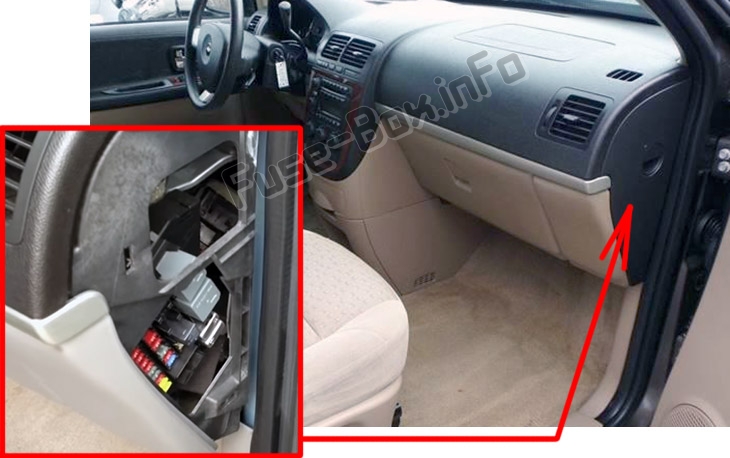
It is located on the passenger’s side of the instrument panel, behind the cover.
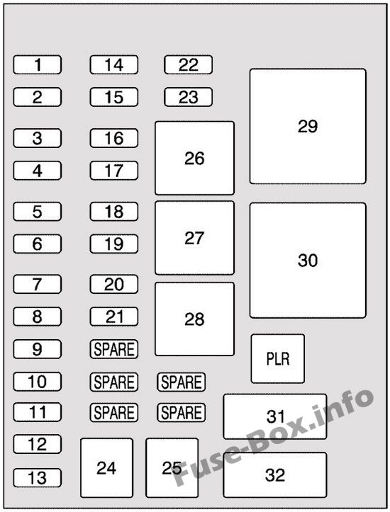
Assignment of the mini fuses in the Instrument Panel
Fuse Data
Full access is available to registered users — log in or register.
Log in or register
No. Description 1 Trunk, Door Locks 2 Electronic Level Control 3 Rear Wiper 4 Radio Amplifier, DVD Player 5 Interior Lamps 6 OnStar 7 Keyless Entry Module 8 Cluster, Heating, Ventilation, Air-Conditioning 9 Cruise Switch 10 Steering Wheel Illumination 11 Power Mirror 12 Stoplamp, Turn Lamps 13 Heated Seats 14 Blank 15 Electronic Level Control 16 Heated Mirror 17 Center High-Mounted Stoplamp, Back-up Lamps 18 Blank 19 Canister Vent Solenoid 20 Park Lamps 21 Power Sliding Door 22 Blank 23 Blank 24 Left Power Sliding Door 25 Right Power Sliding Door
This content requires JavaScript and a valid membership to view.
Assignment of the relays in the Instrument Panel
Fuse Data
Full access is available to registered users — log in or register.
Log in or register
No. Description 26 Blank 27 Blank 28 Park Lamps, Taillamps 29 Retained Accessory Power 30 Rear Defog
This content requires JavaScript and a valid membership to view.
Assignment of the circuit breakers in the Instrument Panel
Fuse Data
Full access is available to registered users — log in or register.
Log in or register
No. Description 31 Power Seats 32 Power Window
This content requires JavaScript and a valid membership to view.
Assignment of the additional spots in the Instrument Panel
Fuse Data
Full access is available to registered users — log in or register.
Log in or register
Short-Code Description PLR Fuse Puller
This content requires JavaScript and a valid membership to view.
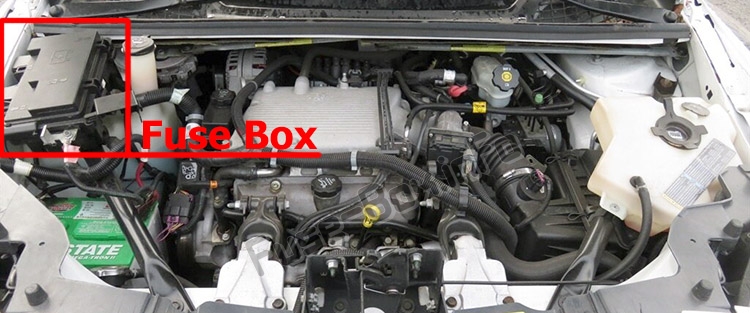
It is located on the passenger’s side of the engine compartment.
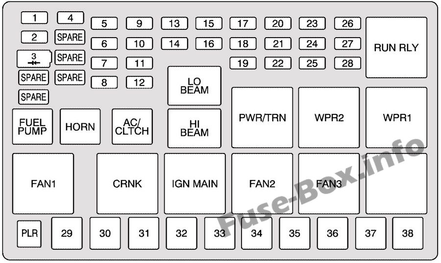
Assignment of the mini fuses in the Engine Compartment
Fuse Data
Full access is available to registered users — log in or register.
Log in or register
No./Name Description 1 Right High Beam 2 Fuel Pump 3 Diode SPARE Spare SPARE Spare 4 Left High Beam SPARE Spare SPARE Spare SPARE Spare 5 Not Used 6 Air Conditioning Clutch 7 Horn 8 Left Low Beam 9 Powertrain Control Module, Electronic Throttle Control 10 Not Used 11 Transmission Solenoid 12 Right Low Beam 13 Anti-lock Brake System 14 Powertrain Control Module Ignition 15 Electronic Ignition 16 Fuel Injector 17 Climate Control, RPA, Cruise Control 18 Electronic Throttle Control 19 Engine Sensor, Evaporator 20 Airbag 21 Not Used 22 2005-2006: Emission, All-Wheel Drive 23 Auxiliary Power 24 Front Windshield Washer 25 AC/DC Inverter 26 Rear Blower 27 Front Blower 28 Front Windshield Wiper
This content requires JavaScript and a valid membership to view.
Assignment of the FMX/J-Case fuses in the Engine Compartment
Fuse Data
Full access is available to registered users — log in or register.
Log in or register
No. Description 29 Fan 1 30 Starter Solenoid 31 Anti-lock Brake System Motor 32 Blank 33 Fan 2 34 Front Blower High 35 Battery Main 3 36 Rear Defogger 37 Battery Main 2 38 2005: Battery Main 1
This content requires JavaScript and a valid membership to view.
Assignment of the relays in the Engine Compartment
Fuse Data
Full access is available to registered users — log in or register.
Log in or register
Short-Code Description RUN RLY Starter LO BEAM Low Beam FUEL PUMP Fuel Pump HORN Horn AC/CLTCH Air-Conditioning Clutch HI BEAM High Beam PWR/TRN Powertrain WPR2 Wiper 2 WPR1 Wiper 1 FAN 1 Fan 1 CRNK Crank IGN MAIN Ignition Main FAN2 Fan 2 FAN3 Fan 3 BLANK Not Used
This content requires JavaScript and a valid membership to view.
Assignment of the additional spots in the Engine Compartment
Fuse Data
Full access is available to registered users — log in or register.
Log in or register
Short-Code Description PLR Fuse Puller
This content requires JavaScript and a valid membership to view.