Explore Chrysler 200 fuse box diagrams in this straightforward guide aimed at giving you quick answers instead of long searches. Here we focus on the first-generation Chrysler 200 (2010–2014) and provide fuse diagrams for 2011, 2012, 2013 and 2014 , along with the location of the fuse panels and the assignment of each fuse , helping you understand the car’s electrical layout with minimal hassle.
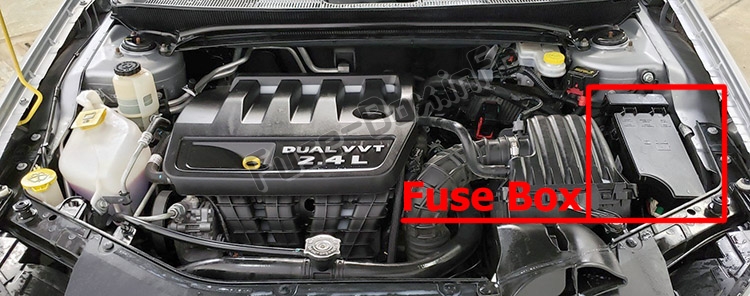
The Integrated Power Module is located in the engine compartment near the air cleaner assembly.
A label that identifies each component may be printed on the inside of the cover.
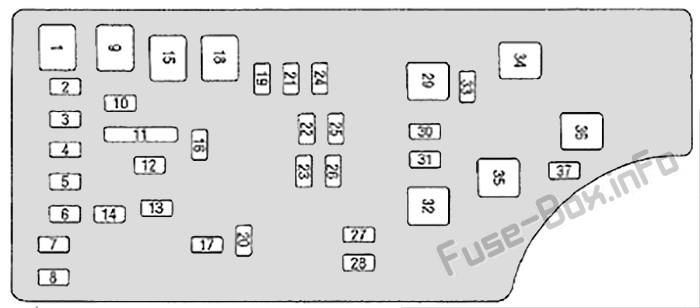
Assignment of fuses in the Integrated Power Module
Fuse Data
Full access is available to registered users — log in or register.
Log in or register
Cavity Cartridge Fuse Mini Fuse Description 1 40 Amp Green — Power Top Module -If Equipped 2 — 20 Amp Yellow Brake Vacuum Pump 3 10 Amp Red Center High Mounted Stop Light (CHMSL)/ Brake Switch 4 — 10 Amp Red Ignition Switch 5 — 20 Amp Yellow Trailer Tow – If Equipped 6 — 10 Amp Red Power Mirror Switch/ Climate Controls 7 — 30 Amp Green Ignition Off Draw (IOD) Sense 1 8 — 30 Amp Green Ignition Off Draw (IOD) Sense 2 9 40 Amp Green Battery Feed – Power Seats – If Equipped 10 20 Amp Yellow Instrument Panel/ Power Locks/ Interior Lights 11 15 Amp Lt Blue Selectable Power Outlet (Inside Center Arm Rest) 12 — 20 Amp Yellow — 13 — 20 Amp Yellow Ignition/Cigar Lighter 14 — 10 Amp Red Instrument Panel 15 40 Amp Green — Radiator Fan Relay 16 — 15 Amp Lt. Blue Sunroof – If Equipped 17 10 Amp Red Wireless Control Module (WCM)/ Clock/Steering Control Module (SCM) 18 40 Amp Green — Auto Shutdown (ASD) Relay 19 — 20 Amp Yellow Audio Amplifier -If Equipped 20 — 15 Amp Lt. Blue Radio 21 — 10 Amp Red Siren – If Equipped 22 10 Amp Red Ignition Run -Climate Controls/ Hot Cupholder -If Equipped 23 — 15 Amp Lt. Blue Auto Shutdown (ASD) Relay 3 24 — 25 Amp Natural Sunroof – If Equipped 25 10 Amp Red Ignition Run — Heated Mirrors -If Equipped 26 — 15 Amp Lt. Blue Auto Shutdown (ASD) Relay 2 27 10 Amp Red Ignition Run -Occupant Classification Module (OCM)/ Occupant Restraint Controller (ORC) 28 10 Amp Red Ignition Run — Occupant Classification Module (OCM)/ Occupant Restraint Controller (ORC) 29 — — Hot Car (No Fuse Required) 30 — 20 Amp Yellow Ignition Run – Heated Seats – If Equipped 31 — — Spare 32 30 Amp Pink — Auto Shutdown (ASD) Relay 1 33 10 Amp Red Switch Bank/ Diagnostic Link Connector/ Powertrain Control Module (PCM) 34 30 Amp Pink Anti-Lock Brakes (ABS) Module – If Equipped/Electronic Stability Control (ESC) Module – If Equipped 35 40 Amp Green Anti-Lock Brakes (ABS) Module – If Equipped/Electronic Stability Control (ESC) Module – If Equipped 36 30 Amp Pink Passenger Door Module (PDM)/Driver Door Module (DDM) 37 — 25 Amp Natural Power Top Module -If Equipped
This content requires JavaScript and a valid membership to view.
")