Explore Chrysler Aspen fuse box diagrams in this straightforward guide that keeps things simple. Here we cover the Chrysler Aspen (2006–2009) and provide fuse diagrams for 2007, 2008 and 2009, along with the location of the fuse panels and the assignment of each fuse and relay, making electrical fixes a little less mysterious.
Ignition Run/Start for Next Generation Controller (NGC), Integrated Power Module (IPM), AC Relay and Fuel Pump Relay
F4
10 Amp Red
Door Node and Non-Memory Power Mirror Switch Battery Feed
F5
(2) 10 Amp Red
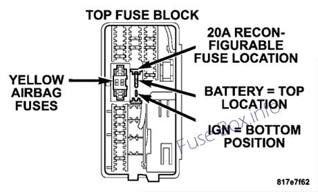
Airbags (2 Fuses in Yellow Holder)
F6
2 Amp Clear
Ignition Run/Start Unlock
F7
25 Amp Natural
Radio Battery Feed
F8
10 Amp Red
Ignition Run/Start for Cluster/Transfer Case/Seat Sw. Back lighting
F9
10 Amp Red
Satellite Digital Audio Receiver (SDAR)/ Digital Video Disc (DVD) Battery Feed
F10
10 Amp Red
Spare
F11
10 Amp Red
Heated Mirrors
F12
20 Amp Yellow
Cluster Battery Feed
F13
10 Amp Red
Ignition Run HVAC Module/Heated Rear Glass (EBL) Relay
F14
10 Amp Red
ABS Module Ignition Run
F15
15 Amp Blue
Battery Feed Blue Tooth, Compass/Trip Computer (CMTC), Sentry Key Diagnostics
F16
20 Amp Yellow
Reconfigurable Power Outlets
F17
20 Amp Yellow
Ignition Run / Rear Park Assist / Second Row Heated Seats
F18
20 Amp Yellow
Cigar Lighter Ignition
F19
10 Amp Red
Spare Fuse
F20
15 Amp Blue
Heating & Air Conditioning w/ATC Only Battery Feed
F21
25 Amp Natural
Amplifier Battery Feed
CB1
25 Amp Circuit Breaker
Sunroof Motor, Power Window
To configure the outlets, be sure the ignition is OFF before removing the fuse. The “reconfigurable” fuse location is a special design that allows the fuse to be installed in two different ways. If the fuse is located in the “Upper or Top Position” the outlets will work at all times. If the fuse is located in the “Lower or Bottom Position” the power outlets will only work when the ignition is ON.
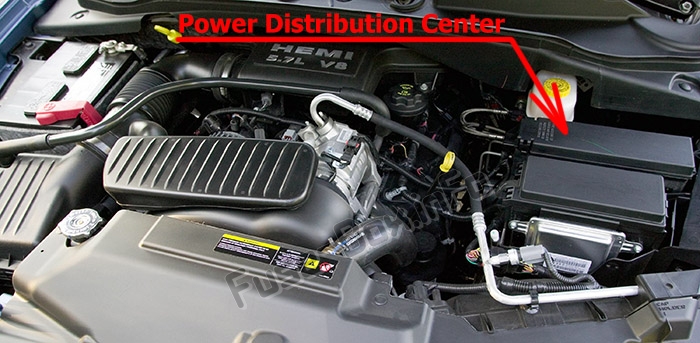
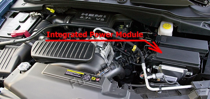
Engine compartment
Power Distribution Center
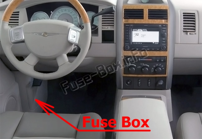
Fuse box location
Power Distribution Center is located in the left side of the engine compartment.
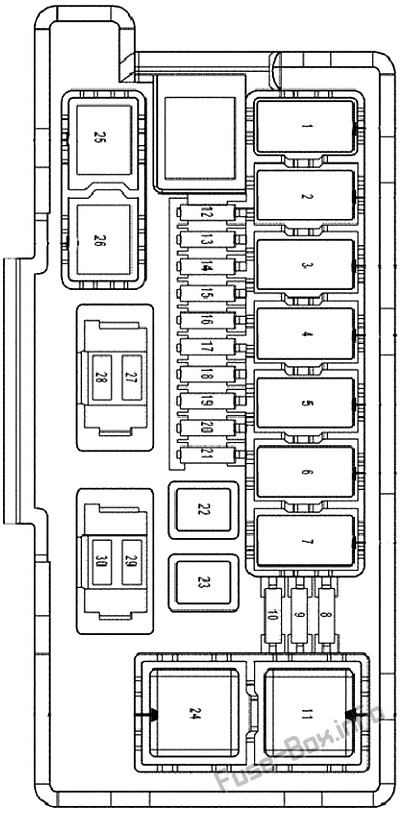
A description of each fuse and component may be stamped on the inside cover, otherwise the cavity number of each fuse is stamped on the inside cover
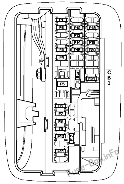
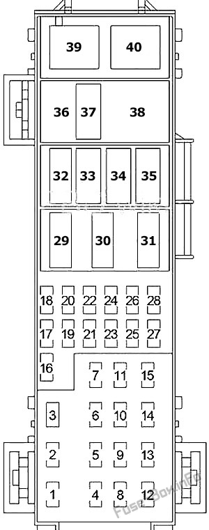
Fuse box diagram
Assignment of fuses in the Power Distribution Center
Fuse Data
Full access is available to registered users — log in or register.