Explore Chrysler Cirrus fuse box diagrams in this quick, professional guide that makes electrical troubleshooting a bit easier. Here we cover the Chrysler Cirrus (1994–2000) and provide fuse diagrams for 1995, 1996, 1997, 1998, 1999 and 2000 , along with the location of the fuse panels and the assignment of each fuse and relay , helping you solve issues without the usual frustration.
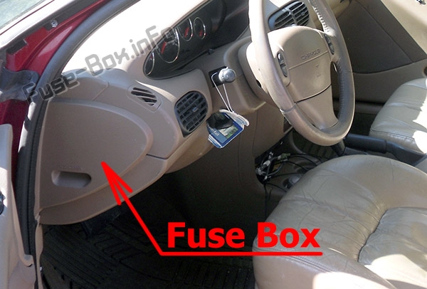
It is located behind the cover on the driver’s side of the dashboard. Pull the cover straight away from the instrument panel for access.
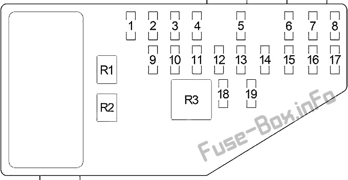
Assignment of fuses in the instrument panel
Fuse Data
Full access is available to registered users — log in or register.
Log in or register
№ Amp Rating Description 1 30 Blower Motor 2 10 / 20 Right Headlamp (High Beam), Daytime Running Lamp Module (Convertible – 20A) 3 10 / 20 Left Headlamp (High Beam) (Convertible – 20A) 4 15 Back-Up Lamp (Back-Up Lamp Switch (M/T), Transmission Range Sensor (A/T)), Power Top Relay (Convertible), Daytime Running Lamp Module, Power Door Lock Switch, Power Mirror Switch, Automatic Day/Night Mirror, Steering Proportional Steering Module 5 10 Dome Lamp, Data Link Connector, Power Antenna, Overhead Map Lamp, Trunk Lamp, Traveler, Body Control Module, Radio, Glove Box Lamp, Visor/Vanity Lamp, Universal Garage Door Opener, Automatic Day/Night Mirror, Illuminated Entry Relay, Courtesy Lamp, Power Door Lock Switch, Door Arm/Disarm Switch, Key-In Halo Lanp, Sunroof Control Module 6 10 Heated Mirror, A/C Heater Control 7 15 / 20 1995-1997: Headlamp Switch (15A); 8 20 Cigar Lighter/Power Outlet, Horn Relay 9 15 Body Control Module 10 20 Rear Fog Lamp Switch, Daytime Running Lamp Module 11 10 Body Control Module, Instrument Cluster, Autostick Switch, Transmission Control Module 12 10 Left Headlamp (Low Beam), Daytime Running Lamp Module 13 20 Right Headlamp (Low Beam), Front Fog Lamp Switch 14 10 Radio 15 10 Combination Flasher, Seat Belt Control Module (Convertible), Intermittent Wiper Relay, Wiper (High/Low) Relay, Rear Window Defogger Relay 16 10 Airbag Control Module 17 10 Airbag Control Module 18 20 Circuit Breaker: Power Seat Switch, Decklid Release Relay 19 20 Circuit Breaker: Power Window, Master Power Window Switch, Window Timer Module, Sunroof Control module Relays R1 Headlamp Delay R2 Horn R3 Rear Window Defogger
This content requires JavaScript and a valid membership to view.
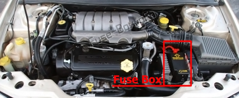
Assignment of fuses in the engine compartment
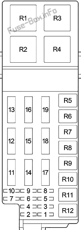
Fuse Data
Full access is available to registered users — log in or register.
Log in or register
№ Amp Rating Description 1 10 O2 Sensor Downstream 2 20 Anti-lock braking system 3 20 Transmission Control Module, Transmission Control Relay 4 20 Stop Lamp Switch, Instrument Panel Fuses: “5” 5 20 Automatic Shut Down Relay (Fuel Injectors, Ignition Coil Pack (2.0L and 2.4L), Noise Suppressor (2.0L and 2.4L), Generator, Oxygen Sensor Upstream, Distributor (2.5L) EGR Solenoid, Fuse: “1”), Powertrain Control Module 6 20 Combination Flasher, Sentry Key Immobilizer Module 7 10 Ignition Switch (Instrument Panel Fuses: “11”) 8 20 Starter Relay, Fuel Pump Relay, Ignition Switch (Body Control Module, Clutch Interlock Switch (M/T), Transmission Control Module (EATX), Instrument Panel Fuses: “14”, “15”, “17”, Engine Compartment Fuses: “9”, “10”) 9 10 A/C Compressor Clutch Relay, Radiator Fan (High Speed) Relay, Radiator Fan (Low Speed) Relay, Fuel Pump Module, Instrument Cluster, Sentry Key Immobilizer Module, Brake Shift Interlock Solenoid 10 10 Fuel Pump Relay, Powertrain Control Module, ABS 11 20 Seat Belt Control Module (Convertible) 12 40 Rear Window Defogger Relay 13 40 Anti-lock braking system 14 40 Instrument Panel Fuses: “7”, “8” 15 40 Headlamp Switch, Headlamp Delay Relay (Body Control Module, Headlamp Switch, Instrument Panel Fuses: “12”, “13”), Instrument Panel Fuses: “9”, “10””18″ 16 40 Ignition Switch (Instrument Panel Fuses: “1”, “4”, “16”, “19”) 17 40 Power Top Up/Down Relays (Convertible) 18 40 Intermittent Wiper Relay (Wiper (High/Low) Relay) 19 40 A/C Compressor Clutch Relay, Radiator Fan (High Speed) Relay, Radiator Fan (Low Speed) Relay Relays R1 Radiator Fan (High Speed) R2 Automatic Shut Down R3 Radiator Fan (Low Speed) R4 Starter R5 – R6 A/C Compressor Clutch R7 Power Tow (Convertible) R8 Intermittent Wiper R9 Wiper (High/Low) R10 Fuel Pump R11 Transmission Control R12 –
This content requires JavaScript and a valid membership to view.