Explore Dodge Journey fuse box diagrams in this easy-to-read guide that breaks down the electrical layout of the refreshed first-generation model. Here we cover the facelifted Dodge Journey (2011–2020) and provide fuse diagrams for 2011, 2012, 2013, 2014, 2015, 2016, 2017, 2018, 2019 and 2020 , along with the location of the fuse panels and the assignment of each fuse , giving you a clear reference for tracking down electrical issues or performing routine work.
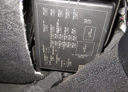
The interior fuse panel is located on the passenger side under the instrument panel.
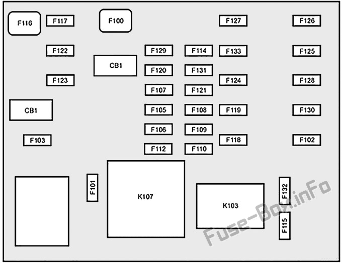
Assignment of the interior fuses
Fuse Data
Full access is available to registered users — log in or register.
Log in or register
No. Cartridge Fuse Mini-Fuse Description F100 30 Amp Pink – 110V AC Inverter – If Equipped F101 – 10 Amp Red Interior Lights F102 — 20 Amp Yellow Cigar Lighter in Instrument Panel/Left Rear Power Outlet F103 — 20 Amp Yellow Power Outlet in Console Bin/Power Outlet in Rear of Console F105 – 20 Amp Yellow Heated Seats – If Equipped F106 – 20 Amp Yellow Rear Power Outlet F107 – 10 Amp Red Rear Camera – If Equipped F108 – 15 Amp Blue Instrument Panel F109 – 10 Amp Red Climate Control/HVAC F110 – 10 Amp Red Occupant Restraint Controller F112 – 10 Amp Red Spare F114 – 20 Amp Yellow Rear HVAC Blower/Motor F115 – 20 Amp Yellow Rear Wiper Motor F116 30 Amp Pink – Rear Defroster (EBL) F117 – 10 Amp Red Heated Mirrors F118 – 10 Amp Red Occupant Restraint Controller F119 – 10 Amp Red Steering Column Control Module F120 – 10 Amp Red All Wheel Drive – If Equipped F121 – 15 Amp Blue Wireless Ignition Node F122 – 25 Amp Clear Driver Door Module F123 – 25 Amp Clear Passenger Door Module F124 – 10 Amp Red Mirrors F125 – 10 Amp Red Steering Column Control Module F126 – 25 Amp Clear Audio Amplifier F127 – 20 Amp Yellow Trailer Tow – If Equipped F128 – 15 Amp Blue Radio F129 – 15 Amp Blue Video/DVD – If Equipped F130 – 15 Amp Blue Climate Control/Instrument Panel F131 — 10 Amp Red Passenger Assistance /Hands Free System -If Equipped F132 – 10 Amp Red Tire Pressure Module F133 – 10 Amp Red Cyber Security Gateway -If Equipped
This content requires JavaScript and a valid membership to view.
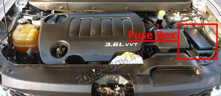
The power distribution center (PDC) is located in the engine compartment.
A label that identifies each component is printed on the inside of the cover.
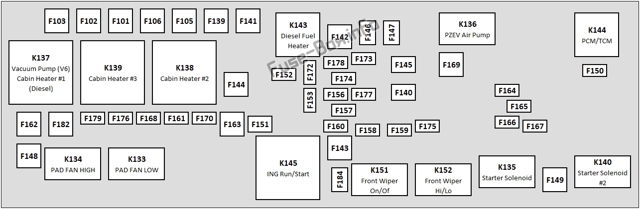
Assignment of the under-hood fuses
Fuse Data
Full access is available to registered users — log in or register.
Log in or register
Cavity Cartridge Fuse Mini-Fuse Description F101 60 Amp Yellow – Interior Power Distribution Center Rail F102 60 Amp Yellow – Interior Power Distribution Center Rail F103 60 Amp Yellow – Interior Power Distribution Center Rail F105 60 Amp Yellow Interior Power Distribution Center Rail Ignition Run Relay F106 60 Amp Yellow — Interior Power Distribution Center Rail Run/ Accessory Relays F139 40 Amp Green – Climate Control System Blower F140 30 Amp Pink – Power Locks F141 40 Amp Green – Anti-Lock Brake System F142 40 Amp Green – Glow Plugs – If Equipped F143 40 Amp Green – Exterior Lights 1 F144 40 Amp Green – Exterior Lights 2 F145 30 Amp Pink – To Body Computer – Lamp F146 30 Amp Pink – Spare F147 30 Amp Pink – Spare F148 40 Amp Green – Radiator Fan Motor F149 30 Amp Pink – Starter Solenoid F150 – 25 Amp Clear Powertrain Control Modules F151 30 Amp Pink – Headlamp Washer Motor – If Equipped F152 – 25 Amp Clear Diesel Fuel Heater – If Equipped F153 – 20 Amp Yellow Fuel Pump F156 – 10 Amp Red Brake/Electronic Stability Control Module F157 – 10 Amp Red Power Transfer Unit Module – If Equipped F158 – 10 Amp Red Active Hood Module – If Equipped F159 – 10 Amp Red Spare F160 – 20 Amp Yellow Interior Lights F161 – 20 Amp Yellow Horn F162 40 Amp Red/20 Amp Lt. Blue — Cabin Heater #1 /Vacuum Pump – If Equipped F163 50 Amp Red – Cabin Heater #2 – If Equipped F164 – 25 Amp Clear Powertrain Auto Shutdown F165 – 20 Amp Yellow Powertrain Shutdown F166 – 20 Amp Yellow Spare F167 – 30 Amp Green Powertrain Shutdown F168 – 10 Amp Red Air Conditioner Clutch F169 40 Amp Green Emissions – Partial Zero Emissions Vehicle Motor F170 15 Amp Blue Emissions – Partial Zero Emissions Vehicle Actuators F172 – 20 Amp Yellow Spare F173 – 25 Amp Clear Anti Lock Brake Valves F174 – 20 Amp Yellow Siren – If Equipped F175 – 30 Amp Green Spare F176 – 10 Amp Red Powertrain Control Modules F177 – 20 Amp Yellow All Wheel Drive Module – If Equipped F178 – 25 Amp Clear Sunroof – If Equipped F179 – 10 Amp Red Battery Sensor F181 100 Amp Blue — Electrohydraulic Steering (EHPS) – If Equipped F182 50 Amp Red – Cabin Heater #3 – If Equipped F184 30 Amp Pink – Front Wiper Motor
This content requires JavaScript and a valid membership to view.
")