Explore Dodge Sprinter fuse box diagrams in this concise guide that makes the van’s electrical layout easier to work with, whether you’re maintaining a work vehicle or chasing an electrical glitch. Here we cover the second-generation Dodge Sprinter (2007–2010) and provide fuse diagrams for 2007, 2008, 2009 and 2010 , along with the location of the fuse panels and the assignment of each fuse , helping you identify the right circuits quickly and efficiently.
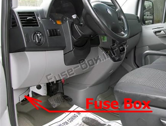
It is located under the instrument panel (on the driver’s side), under the cover.
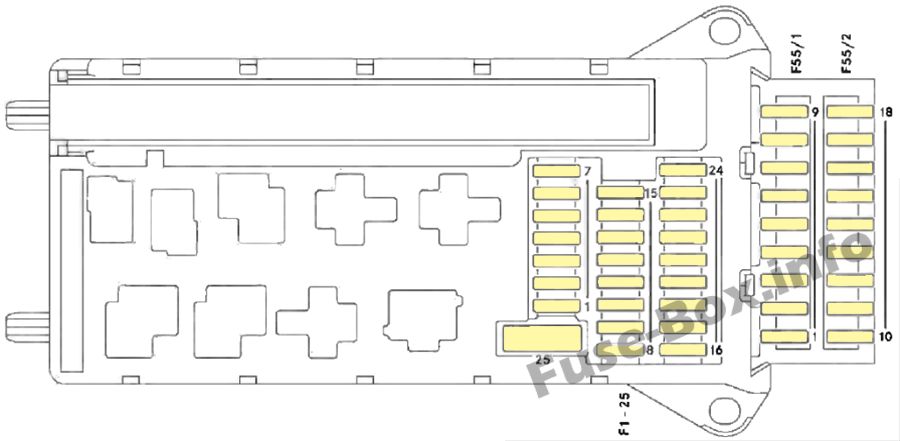
Assignment of the fuses in the Instrument Panel Fuse Box
Fuse Data
Full access is available to registered users — log in or register.
Log in or register
№ Consumer Amp. 1 Horn 15 A 2 Electric steering lock ESTL (electronic ignition switch EIS) 25 A 3 Terminal 30 Z. vehicles with gasoline engine/electronic ignition switch ElS/instrument cluster 10 A 4 Light switch/center console switch unit 5 A 5 Windshield wipers 30 A 6 Fuel pump 15 A 7 MRM (Jacket tube module) 5 A 8 Terminal 87 (2) 20 A 9 Terminal 87 (3) 20 A 10 Terminal 87 (4) 10 A 11 Terminal 15 R vehicle 15 A 12 Airbag control unit 10 A 13 Cigarette lighter/glove box lighting/radio 15 A 14 Diagnostic socket/light switch/instrument cluster 5 A 15 Front heating system 5 A 16 Terminal 87 (1) 10 A 17 Airbag control unit 10 A 18 Terminal 15 vehicle, brake lamp switch 7.5 A 19 Interior lights 7.5 A 20 Power window co-driver’s side/terminal 30/2 signal acquisition and actuation module SAM 25 A 21 Engine control unit 5 A 22 Antilock Brake System (ABS) 5 A 23 Starter motor 25 A 24 Diesel engine components 10 A 25 12V socket on the bottom of the center console 25 A Fuse block F55/1 1 Control panel, left door 25 A 2 Diagnostic socket 10 A 3 Brake system (valves) 25 A 4 Brake system (delivery pump) 40 A 5 Terminal 87 (5), vehicles with gasoline engine 7.5 A 6 Terminal 87 (6), vehicles with gasoline engine 7.5 A 7 Headlamp cleaning system 30 A 8 Anti-theft alarm system (ATA) 15 A 9 Unassigned n Fuse block F55/2 10 Radio 15 A 11 Telephone 7.5 A 12 Front blowers 30 A 13 Unassigned 9 14 Seat heating/center console switch unit 30 A 15 Non MB-body electrics 10 A 16 Heating, rear heating/ Tempmatic (air-conditioning system), front/CD-player 10 A 17 Motion detector/convenience interior lighting/ satellite radio 10 A 18 Air conditioning in the rear 7.5 A
This content requires JavaScript and a valid membership to view.
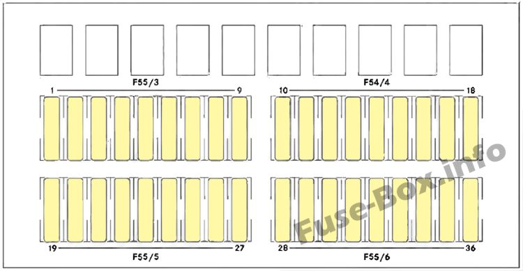
Assignment of the fuses in the Fuse Box under driver’s seat
Fuse Data
Full access is available to registered users — log in or register.
Log in or register
№ Consumer Amp. 1 Mirror adjustment 5 A 2 Rear window wiper 30 A 3 Reversing camera/ telephone 5 A 4 Operating speed governor (ADR)/PTO/trailer connection unit AAG 7.5 A 5 Terminal 87 electronic transmission control ETC, control unit 10 A 6 Unassigned – 7 Electronic selector level module ESM 7.5/15 A 8 Terminal 15 body builder, drop side/3-way tipper 10 A 9 Roof ventilator/audio signal equipment 15 A 10 Terminal 30, tapping wire body builder 25 A 11 Terminal 15, tapping wire body builder 15 A 12 D+, tapping wire body builder 10 A 13 Auxiliary indication modul 10 A 14 Trailer socket 20 A 15 Trailer recognition device 25 A 16 Tir pressure monitoring system (TPMS)/ Parktronic system (PTS) 7.5 A 17 PSM control unit 25 A 18 PSM control unit 25 A 19 Overhead control panel/ sliding sunroof 5/25 A 20 Clearance lamps 7.5 A 21 Rear window heating 30/15 A 22 Rear window heating 2 15 A 23 12V socket rear left, load/passenger compartment 15 A 24 12V socket driver’s seat base 15 A 25 12V socket rear right, load/passenger compart-ment/Auxiliary heating blower speed 1 15 A 26 Auxiliary heating 25 A 27 Heater booster 25/20 A 28 Air conditioning in the rear 30 A 29 Unassigned – 30 Unassigned – 31 Blower unit, rear heating 30 A 32 Unassigned – 33 Electric sliding door, right 30 A 34 Electric sliding door, left 30 A 35 Brake booster 30 A 36 Unassigned –
This content requires JavaScript and a valid membership to view.
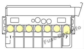
Pre-fuse box is located in the battery compartment in the footwell on the left-hand side of the vehicle F59 (remove the lining and metal cover in front of the driver’s seat)
Assignment of the fuses in the Pre-Fuse Box
Fuse Data
Full access is available to registered users — log in or register.
Log in or register
№ Consumer Amp. 1 Pre-glow relay/secondary air pump 80/40 A 2 Engine fan air-conditioning system 80 A 3 Signal acquisition and actuation module SAM/fuse and relay block SRB 80 A 4 Auxiliary battery in the engine compartment 150 A 5 Termina130 fuse boxes, signal acquisition and actuation module SAM/fuse and relay block SRB 150 A 6 Connecting point in driver’s seat base Bridge 7 Heater booster (PTC) 150 A
This content requires JavaScript and a valid membership to view.
")