The Ford F-150 Lightning , a revolutionary battery-electric pickup truck, has been available from 2022 to the present . Combining the rugged capability of the F-Series with cutting-edge electric technology, the Lightning offers impressive performance, innovation, and sustainability.
In this article, you will find fuse box diagrams for Ford F-150 Lightning models produced between 2022 and 2025 , including years 2022, 2023, 2024, and 2025 . These diagrams provide essential information about the fuse layout , helping owners and technicians troubleshoot and maintain the vehicle’s electrical systems effectively.
What’s Included:
Fuse Box Diagrams : Clear, easy-to-read visuals for quick identification of fuses and relays.Fuse Panel Locations : Step-by-step instructions on where to locate the fuse panels inside your Ford F-150 Lightning.Fuse Assignments : Comprehensive descriptions of each fuse and relay’s function for diagnostics and repairs.
Whether you’re addressing electrical issues, replacing a blown fuse, or conducting routine maintenance, this guide is an essential resource for Ford F-150 Lightning owners and technicians. It ensures your vehicle’s systems remain functional and reliable.
Keep your Ford F-150 Lightning (2022–Present) running smoothly with this detailed fuse box guide!
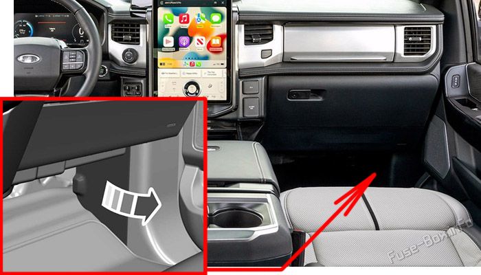
The fuse panel is in the right-hand side of the passenger footwell behind a trim panel.
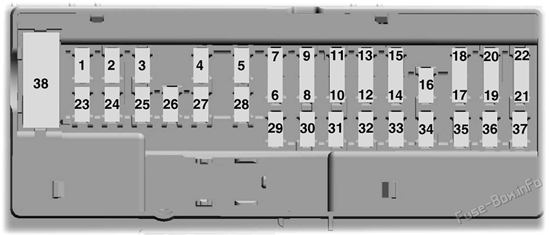
Assignment of the fuses in the passenger compartment
Fuse Data
Full access is available to registered users — log in or register.
Log in or register
№ Amps Protected Component 1 – Not used. 2 10A Driver window switch-delayed accessory feed. 3 7.5A Wireless accessory charging module. 4 20A Not used (spare). 5 – Not used. 6 10A Driver window switch-powered at all times. 7 10A Gearshift module. 8 5A Telematics control module. 9 5A Inclination sensor. 10 – Not used. 11 – Not used. 12 7.5A Climate control module. 13 7.5A Instrument cluster. 14 15A Frunk module. 15 15A Integrated control module. 16 – Not used. 17 7.5A Not used (spare). 18 7.5A Not used (spare). 19 5A Headlamp switch. 20 5A Start switch. 21 5A Trailer brake switch. 22 5A Not used (spare). 23 30A Driver door control module. 24 30A Moonroof. 25 20A Not used (spare). 26 30A Passenger door control module. 27 30A Not used (spare). 28 30A Amplifier. 29 15A Adjustable pedal switch. 30 5A Not used (spare). 31 10A Driver status monitor. 32 20A Radio. 33 – Not used. 34 30A Run/start relay. 35 5A Not used (spare). 36 15A Rear heated seat module. 37 20A Not used (spare). 38 30A CB Rear window switches.
This content requires JavaScript and a valid membership to view.
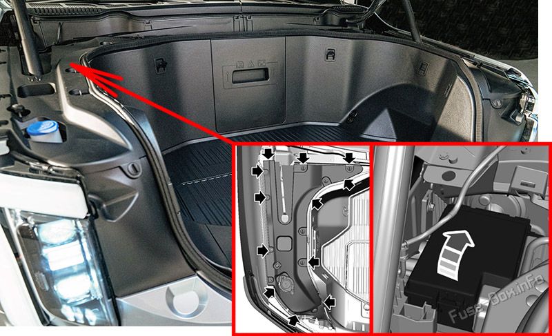
To access, first remove the right-side frunk cover then remove the fuse box cover:
Start at the rear edge of the right hand-side and work toward the front of the cover.
Pull upward at the clip locations shown to release the clips.
Remove the frunk cover.
Remove the top cover.
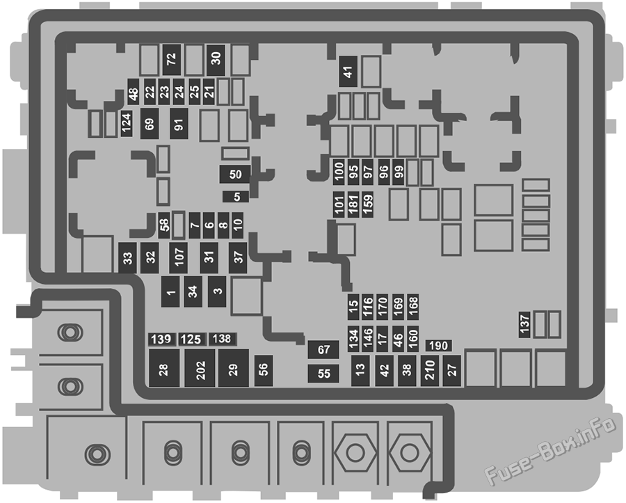
Assignment of the fuses in the front compartment
Fuse Data
Full access is available to registered users — log in or register.
Log in or register
№ Amps Protected Component 1 40A Body control module. 3 40A Body control module. 5 5A Primary drive control module. 6 25A Powertrain control module. 7 20A Powertrain control module heater cooling pump. 8 20A A/C control module. 10 10A Auxiliary power point. 13 40A Blower motor. 15 25A Horn. 17 5A Charge port status indicator. 21 10A Not used (spare). 22 10A Electronic power assist steering module. 23 10A Anti-lock brake system module. 24 10A Primary drive control module. 25 10A Trailer camera module. 27 25A Primary drive control module fluid pump. 28 50A Anti-lock brake system module. 29 50A Anti-lock brake system module. 30 40A Driver seat module. 31 30A Passenger power seat. 32 20A Power point. 33 20A Not used (spare). 34 20A Auxiliary power point. 37 30A Power tailgate module. 38 40A Climate control module. 41 25A Heated rear window. 42 30A Trailer brake control module. 46 10A Battery charger control module. 48 20A Rear heated seat module. 50 40A Heated backlite. 55 30A Trailer tow park lamps. 56 20A Trailer tow stoplamps. 58 10A Trailer tow backup lamps. 67 25A Secondary drive control module fluid pump. 69 30A Front wiper motor. 72 40A Front trunk module. 91 20A Trailer tow lighting module. 95 15A Primary drive control module. 96 20A Coolant pump. 97 10A A/C pressure and temperature sensor. 99 15A Secondary drive control module. 100 25A Left-hand headlamp. 101 25A Right-hand headlamp. 107 30A Trailer tow lighting module. 116 10A Second battery charger control module. 124 5A Rain sensor. 125 10A USB smart charger 1. 134 25A Driver multi-contour seat. 137 20A Advanced driver assistance system module. 138 10A Tailgate release solenoid. 139 5A USB smart charger 3. 146 15A Battery energy control module. 159 5A Direct current/direct current converter. 160 10A Smart datalink connector. 168 15A Battery energy control module. 169 20A Coolant pump. 170 20A High voltage battery coolant pump. 181 5A Headlamp control module. 190 5A Not used (spare). 202 60A Body control module. 210 30A Body control module.
This content requires JavaScript and a valid membership to view.