The fourth-generation Ford Mondeo (Mk5), a sleek and versatile mid-size family car, was available from 2014 to 2022. Known for its modern design, advanced technology, and refined performance, this iteration of the Mondeo became a popular choice for drivers seeking both comfort and efficiency.
In this article, you will find fuse box diagrams for Ford Mondeo models produced between 2014 and 2022, covering years 2014, 2015, 2016, 2017, 2018, 2019, 2020, 2021, and 2022. These diagrams provide detailed insights into the fuse layout and relay assignments, helping owners and technicians effectively maintain and troubleshoot the vehicle’s electrical systems.
What’s Included:
Fuse Box Diagrams: Clear, easy-to-read visuals for identifying fuses and relays quickly.
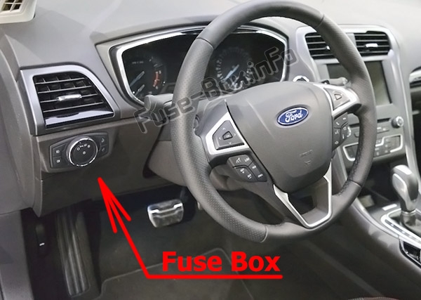
Fuse Panel Locations: Step-by-step instructions on where to find the fuse panels inside your Ford Mondeo.
Fuse Assignments: Comprehensive descriptions of each fuse and relay’s function for accurate diagnostics and repairs.
Whether you’re replacing a blown fuse, addressing an electrical issue, or performing regular maintenance, this guide is an invaluable resource for Ford Mondeo owners and technicians. It ensures the vehicle’s systems remain reliable and functional.
Keep your Ford Mondeo (2014–2022) in excellent condition with this detailed fuse box guide!
The cigar lighter (power outlet) fuses in the Ford Mondeo are:
Fuse №10: Driver Front Auxiliary Power Point
Fuse №16: Console Auxiliary Power Point
Fuse №17: Trunk Auxiliary Power Point (Wagon Only)
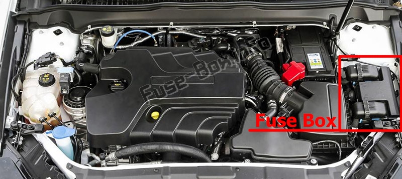
All are located in the Engine Compartment Fuse Box.
Transmission control module. Transmission oil pump.
22
10A
Air conditioning.
23
15 A
Blind spot monitor. Rear view camera. Adaptive Cruise Control. Pre-collision warning indicator. Voltage quality module. Air quality sensor.
24
10A
Not used (spare).
25
10A
Anti-lock brake system.
26
10A
Powertrain control module.
27
—
Not used.
28
10A
Rear washer pump.
29
—
Not used.
30
—
Not used.
31
—
Not used.
32
—
Cooling fan relay.
33
—
Air conditioning relay.
34
15 A
Electric steering column lock.
35
—
Not used.
36
—
Not used.
37
—
Not used.
38
—
Cooling fan relay.
39
—
Cooling fan relay.
40
—
Not used.
41
—
Horn relay.
42
—
Fuel pump relay.
43
—
Not used.
44
5A
Heated washer nozzle.
45
—
Not used.
46
10A
Alternator.
47
10A
Brake on-off switch.
48
20A
Horn.
49
5A
Mass air flow monitor.
49
20A
Fuel heater element-Diesel.
50
10A
Power transfer unit cooling fan.
51
—
Not used.
52
—
Not used.
53
10A
Power seats.
54
5A
Fuel operated heater remote control.
55
5A
Not used (spare).
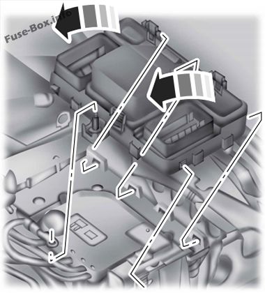
Power Distribution Box – Bottom
Fuse box location
There are fuses located on the bottom of the fusebox.
To access, do the following: 1) Release the two latches, located on both sides of the fusebox. 2) Raise the inboard side of the fusebox from the cradle. 3) Move the fusebox toward the center of the engine compartment. 4) Pivot the outboard side of the fusebox to access the bottom side.
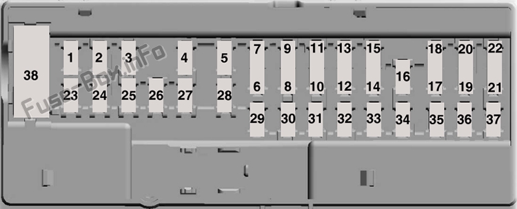
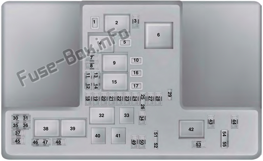
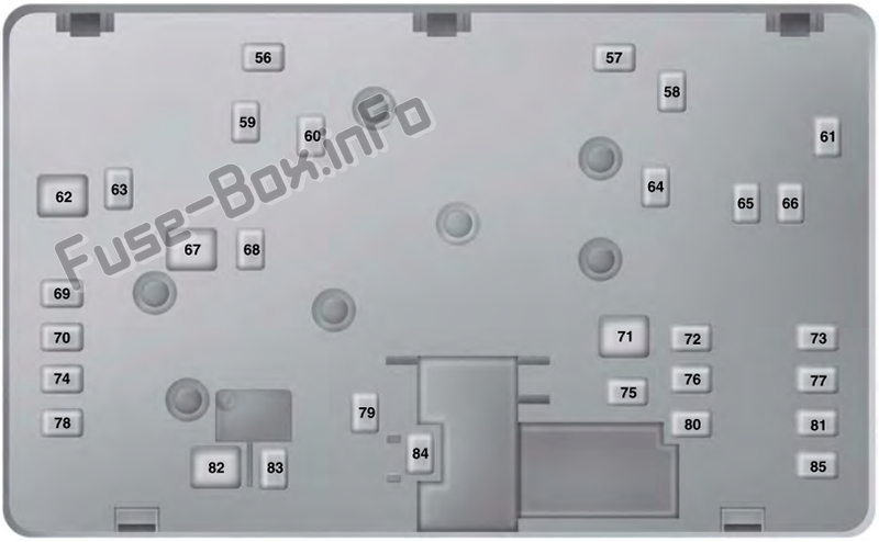
Fuse box diagram
Assignment of the fuses in the Power distribution box (Bottom)
Fuse Data
Full access is available to registered users — log in or register.
 | 2007-2010 | Fuse Panel Location and Diagram")
 | 2010-2014 | Fuse Panel Location and Diagram")