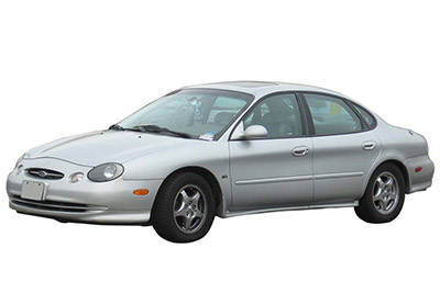
The third-generation Ford Taurus , a full-size sedan known for its innovative design, comfort, and practicality, was produced from 1996 to 1999 . This model featured updated styling and improved technology, making it a reliable choice for families and commuters alike.
In this article, you will find fuse box diagrams for Ford Taurus models produced between 1996 and 1999 , covering years 1996, 1997, 1998, and 1999 . These diagrams provide essential details about the fuse layout and relay assignments, helping owners and technicians efficiently troubleshoot and maintain the vehicle’s electrical systems.
What’s Included:
Fuse Box Diagrams : Clear and detailed visuals for quick identification of fuses and relays.Fuse Panel Locations : Step-by-step guidance on locating the fuse panels inside your Ford Taurus.Fuse Assignments : Comprehensive descriptions of each fuse and relay’s function for accurate diagnostics and repairs.
Whether you are replacing a blown fuse, diagnosing electrical issues, or conducting routine maintenance, this guide is an indispensable resource for Ford Taurus owners and technicians. It ensures your vehicle’s electrical systems remain reliable and functional.
Keep your Ford Taurus (1996–1999) in excellent condition with this detailed fuse box guide!
The cigar lighter (power outlet) fuse in the Ford Taurus is fuse No.21 located in the Instrument Panel Fuse Box .
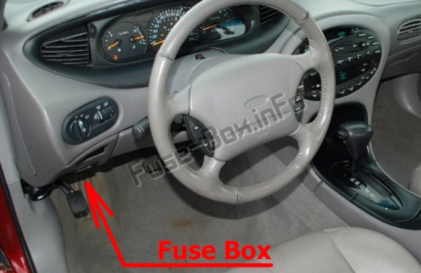
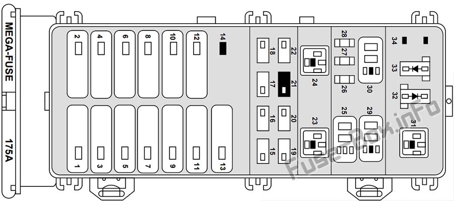
The fuse panel is located below and to the left of the steering wheel by the brake pedal.
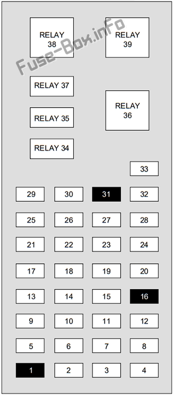
Assignment of the fuses and relays in the Passenger compartment
Fuse Data
Full access is available to registered users — log in or register.
Log in or register
№ Amp Rating Description 1 — Not Used 2 5A Instrument Illumination 3 10A Left Low Beam Headlamp 4 10A Right Low Beam Headlamp 5 5A Brake Shift Interlock, Rear Defroster 6 15A 1996-1997: MLPS switch, backup lamps, speed control, climate control 7 10A 1996-1998: MLPS Switch, Starter Relay 8 5A Power Antenna, RCU (radio control unit), GEM 9 10A 1996-1997: Anti-lock brakes system, Central Temperature Monitor 10 20A 1996-1997: EEEC relay, ignition coil, passive anti-theft system, radio 11 5A 1996-1997: Air bag indicator, instrument cluster 12 5A Instrument Cluster, Autolamps, Transmission Control Switch, ICP (integrated control panel), GEM 13 5A 1996-1998: Air Bag, Blower Motor, EATC (electronic automatic temperature control) 14 5A 1996-1997: Lamp outage indication, Semi-active suspension (SHO only) 15 10A Multi-Function Switch (Turn Signal) 16 — Not Used 17 30A Front Wiper/Washer 18 5A Headlamp Switch 19 15A Rear Wiper/Washer 20 5A 1996-1997: Integrated control panel, remote entry, cigar lighter 21 20A Cigar Lighter 22 5A Power Mirrors, Power Antenna, Decklid Lamps, Autolamp 23 5A 1996-1997: Wiper system, variable assist steering, remote entry, anti-theft 24 5A 1996-1997: Integrated control panel, speedometer, electronic automatic temperature control module 25 10A (DLC) Data Link Connector 26 15A Trunklid 27 10A Battery Saver Relay 28 15A 1996-1997: Brake lamps, stop control 29 15A Multi-Function Swatch, Hazard flashers 30 15A High Beams, Daytime Running Lamps, Instrument Cluster 31 5A 1996-1997: Tail lamp feed 32 10A ICP (Integrated control panel), Heated Mirrors 33 5A Power Windows, Lock Illumination Relay 34 — Battery Saver Relay Relay 35 — Driver Door Unlock Relay Relay 36 — Rear Defroster Relay Relay 37 — Interior Lamp Relay Relay 38 — One Touch Window Down Relay Relay 39 — Accessory Delay Relay
This content requires JavaScript and a valid membership to view.
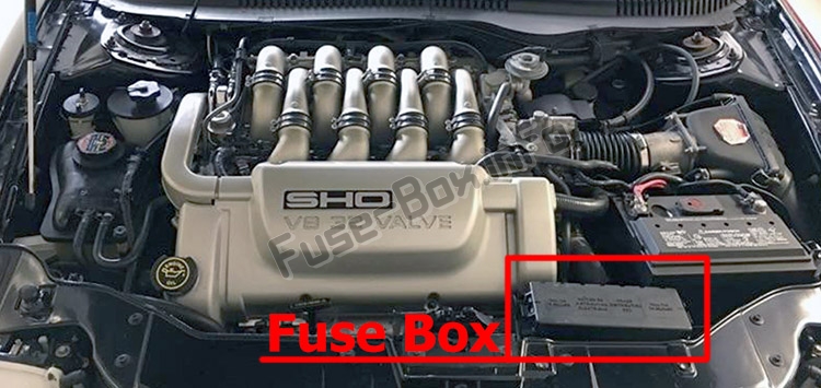
The power distribution box is located in the engine compartment near the battery.
Assignment of the fuses and relays in the Power distribution box
Fuse Data
Full access is available to registered users — log in or register.
Log in or register
№ Amp Rating Description 1 40A Fuse Panel 2 30 A 1996-1997: Constant control relay module 3 40A Ignition Switch, Starter Relay 4 30A 1996-1997: Accessory delay relay 5 40A Ignition Switch 6 30 A / — 1996-1997: Power seats 7 40A Rear Window Defrost Relay 8 30A Thermactor Air ByPass Solenoid, EAM Solid State Relay 9 40A 1996-1997: Constant control relay module 10 20 A 1996-1997: Constant control relay module 11 40A Blower Motor Relay 12 20 A Semi-Active Ride Control Module 13 40A Anti-Lock Brake Module 14 — Not Used 15 15 A Daytime Running Lamps (DRL) Module 16 10A 1996-1998: Air Bag Diagnostic Monitor 17 20A Rear Control Unit, CD Changer 18 30A Anti-Lock Brake Module 19 15 A Horn Relay, Powertrain Control Module (PCM) 20 15 A Headlamp Switch, Autolamp Park Relay 21 — Not Used 22 30A Autolamps Relay, Multi-Function Switch, Headlamp Switch 23 — Blower Motor Relay 24 — Starter Relay 25 — A/C Clutch Relay 26 30A Generator/Voltage Regulator 27 10A A/C Clutch Relay 28 15 A Heated Oxygen Sensors, Canister Vent 29 — Fuel Pump Relay 30 — PCM Relay 31 — Low Speed Cooling Fan Relay 32 — PCM Diode 33 — A/C Clutch Diode 34 — Not Used
This content requires JavaScript and a valid membership to view.