Looking for GMC Sierra EV fuse box diagrams ? This article covers the GMC Sierra EV , available from 2024 , and includes fuse box diagrams for GMC Sierra EV 2024, 2025 and 2026 , along with details about the location of the fuse panels inside the vehicle and a clear explanation of the assignment of each fuse and relay (fuse layout).
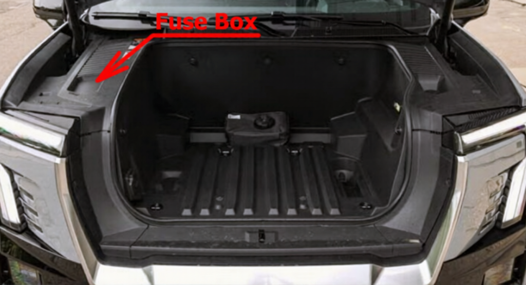
The fuse block is in the under-hood compartment, on the passenger side of the vehicle. Press the clips on the sides and lift the cover to access the fuse block.
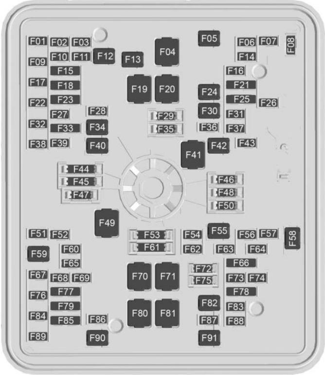
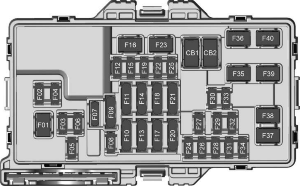
Assignment of the fuses in the front compartment
Fuse Data
Full access is available to registered users — log in or register.
Log in or register
No. Description F1 N/A F2 N/A F3 N/A F4 N/A F5 N/A F6 ACEC – Air Conditioning Electric Compressor F7 ESSCP – Energy Storage System Coolant Pump F8 N/A F9 PECP – Power Electric Cooling Pump F10 N/A F11 N/A F12 N/A F13 TRLR_HD – Trailer Headlights F14 N/A F15 VLM – Vehicle Leveling Module (Air Suspension) / Spare F16 N/A F17 ELM 1 – Exterior Lighting Module 1 F18 SADS – Semi Active Damping System / F19 IECL 2 – Left Internal Electrical Center 2 F20 N/A F21 N/A F22 IRM_ACM – Integrated Refrigerant Module and Air Conditioning Module F23 VICMS – Vehicle Integrated Control Module / F24 N/A F25 N/A F26 N/A F27 PKLPS_TRLR – Trailer Park Lights F28 N/A F29 Spare F30 PUMP_ONE (Coolant Pump 1) F31 N/A F32 N/A F33 Spare / F34 TIM1 – Trailer Interface Module 1 F35 Spare F36 TPIM1_BAT2 – Traction Power Inverter Module 1, Battery 2 F37 N/A F38 TRLR_STP_TRN_LT – Trailer Stop / Turn Left F39 TRLR_STP_TRN_RT – Trailer Stop / Turn Right F40 VLM_M – Vehicle Leveling Module Motor (Air Suspension Compressor) F41 N/A F42 N/A F43 N/A F44 Spare F45 Spare F46 Spare F47 Spare F48 Spare F49 TBPM – Trailer Brake Power Module F50 Spare F51 MIDGATE MOTOR RIGHT (Controls the folding Midgate behind the cab) F52 N/A F53 Spare F54 PFCM – Power Front Closure Module (Power Frunk Control) F55 REAR DEFOG – Rear Window Defogger F56 N/A F57 MINOR ENDGATE HIGH (Tailgate Control Module) F58 FRNT WIPER – Front Windshield Wiper F59 TIM2 – Trailer Interface Module 2 F60 PKLPS_ID – Park Lamps / Identification (Clearance) Lamps F61 Spare F62 ELM 3 – Exterior Lighting Module 3 F63 GLASS BREAK – Glass Breakage Sensor (Anti-theft) F64 N/A F65 ELM 4 – Exterior Lighting Module 4 F66 N/A F67 EMB/GRILL LIGHT – Illuminated Front Emblem / Grille Light F68 HDLP_LT – Left Headlamp F69 MIDGATE LEFT MOTOR (Controls the folding Midgate behind the cab) F70 EBCM 1 – Electronic Brake Control Module 1 F71 DC/AC Inverter (For household-style cabin/bed power outlets) F72 Spare F73 N/A F74 N/A F75 Spare F76 HDLP_RT – Right Headlamp F77 N/A F78 MIDGATE CROSS BAR MOTOR 2 / MIDGATE CROSS BAR MOTOR 1 (Midgate folding mechanism) F79 PCV_PEEV_ALD / FR RADAR/VIRTUAL KEY – Front Radar Sensor / Virtual Key (Phone-as-key module) F80 IECR 2 – Right Internal Electrical Center 2 F81 IECL 1 – Left Internal Electrical Center 1 F82 N/A F83 N/A F84 V2LIM – Vehicle to Load Inverter Module (Allows the truck to power external homes/appliances) F85 Spare / HVS (HIGH VOLTAGE SERVICE DISCONNECT) F86 Horn F87 FRT WSHR PMP – Front Windshield Washer Pump F88 N/A F89 N/A F90 N/A F91 N/A
This content requires JavaScript and a valid membership to view.
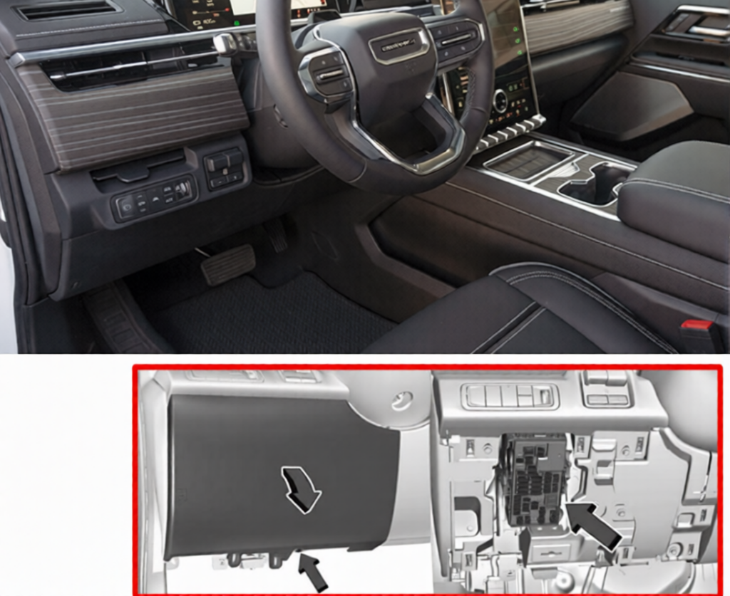
The instrument panel fuse block is on the driver side of the instrument panel, between the steering wheel and the door.
Assignment of the fuses in the interior fuse panel (Driver’s Side)
Fuse Data
Full access is available to registered users — log in or register.
Log in or register
No. Description F1 DRIVER_PWR_ST – Driver Power Seat F2 VKS_TTPM – Virtual Key System / Trailer Tire Pressure Module F3 VECM – Vehicle Energy Control Module F4 BCM 1 – Body Control Module 1 F5 ELM 5 – Exterior Lighting Module 5 F6 PASSENGER DSP – Passenger Display / Digital Signal Processor F7 SPARE F8 TCP – Telematics Control Platform F9 4W_Co_Driver PWR LUMBAR – 4-Way Passenger Power Lumbar / SPARE F10 WCM_VKM / TVR_APA_PFA – Wireless Charger Module / Virtual Key Module / Surround Vision / Advanced Park Assist / Pedestrian Friendly Alert F11 2ND HTD SEAT – 2nd Row Heated Seat / 2nd Row Heated Seat 1 F12 SPARE F13 TPIM / TPIM 2 – Traction Power Inverter Module 2 F14 SPARE F15 SPARE F16 Tonneau Accessory F17 SDM_AOS / SRR – Sensing Diagnostic Module (Airbags) & Automatic Occupant Sensing / Short Range Radar F18 SPARE F19 SPARE F20 OBCM 2 / MSM – On-Board Charging Module 2 / Memory Seat Module F21 HSM ROW / HSM ROW 1 – Heated Seat Module Row 1 F22 SPARE F23 MJR END HIGH – Major Endgate High F24 TPIM 1 & VBAT 1 – Traction Power Inverter Module 1 & Vehicle Battery 1 F25 SPARE F26 TPIM 2 & VBAT 1 – Traction Power Inverter Module 2 & Vehicle Battery 1 F27 DSP – Digital Signal Processor F28 ELM 7 – Exterior Lighting Module 7 F29 SPARE F30 MJR END LOW – Major Endgate Low F31 ELM 2 – Exterior Lighting Module 2 F32 RFR/PLCM – Radio Frequency Receiver / Power Liftgate Control Module F33 MIDGATE CONTROL LOW F34 ACP_VPM – Accessory Power / Video Processing Module F35 AMP – Amplifier F36 CO-DRVR_PWR_ST – Co-Driver (Passenger) Power Seat F37 SPARE F38 ELM 6 – Exterior Lighting Module 6 F39 RT WNDW – Right Hand Power Window F40 LT WNDW – Left Hand Power Window
This content requires JavaScript and a valid membership to view.
Assignment of the circuit breakers in the interior fuse panel (Driver’s Side)
No. Description CB1 N/A CB2 N/A
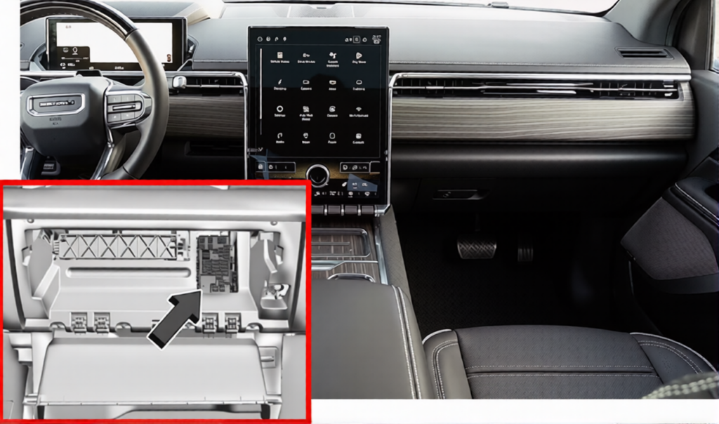
The instrument panel fuse block is located behind the glove box. It is accessible by removing the hush panel located underneath the glove box. To remove the hush panel, remove the four push-pins that secure the hush panel.
Assignment of the fuses in the interior fuse panel (Passenger’s side)
Fuse Data
Full access is available to registered users — log in or register.
Log in or register
No. Description F1 FRT BLWR MTR – Front Blower Motor F2 CPM – Climate Power Module F3 VDM – Vehicle Dynamics Module F4 SPARE F5 BCM 2 – Body Control Module 2 F6 BCM 4 – Body Control Module 4 F7 COIL CLOCK SPRING F8 TBCS/EPB – Trailer Brake Control Switch / Electric Park Brake F9 ESM / SPARE – Electronic Shifter Module / Spare F10 Displays / SPARE F11 CGM / SPARE – Central Gateway Module / Spare F12 Steering Column Lock F13 SPARE / DLC – Data Link Connection (OBD-II Diagnostic Port) F14 BODY MISC / BODY MISC 1 – Body Miscellaneous F15 MISC_IP 1 – Miscellaneous Instrument Panel 1 F16 SPARE F17 SPARE F18 BDY 1 / HDLNR – Body 1 / Headliner F19 VICM TPIM IGN – Vehicle Integration Control Module / Traction Power Inverter Module / Ignition F20 OHC / HUD / ETC – Overhead Console / Head-Up Display / Electronic Toll Collection F21 VCU / VCU 2 – Vehicle Control Unit 2 F22 SPARE F23 SPARE F24 FCM_RLH_UGDO – Forward Camera Module / Roof Light Housing / Universal Garage Door Opener F25 USB_ROW 2 – 2nd Row USB Ports F26 SPARE F27 USB F28 SPARE F29 FRT_HVAC_DIS – Front HVAC Display F30 SPARE F31 BCM 3 – Body Control Module 3 F32 HSWM – Heated Steering Wheel Module F33 SPARE F34 SPARE F35 SPARE F36 SPARE F37 SPARE F38 SPARE F39 SPARE F40 SPARE
This content requires JavaScript and a valid membership to view.
Assignment of the circuit breakers in the interior fuse panel (Passenger’s side)
Fuse Data
Full access is available to registered users — log in or register.
Log in or register
No. Description CB1 APO – Auxiliary Power Outlet Center Console CB2 SPARE
This content requires JavaScript and a valid membership to view.