The first-generation Mercedes-Benz CLS-Class (C219), produced from 2003 to 2010, introduced the world to the concept of the four-door luxury coupe. With its sleek styling, refined interior, and a selection of powerful engines—including AMG variants—the C219 blended performance with sophistication in a way few sedans had done before.
In this article, you will find fuse box diagrams for the Mercedes-Benz CLS-Class, covering models CLS280, CLS300, CLS320, CLS350, CLS500, CLS55 AMG, and CLS63 AMG for the years 2003, 2004, 2005, 2006, 2007, 2008, 2009, and 2010. These diagrams will help you understand the complete fuse layout, including the function and location of each fuse and relay within the vehicle.
What’s Included in This Guide:
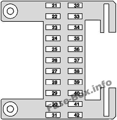
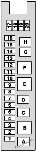
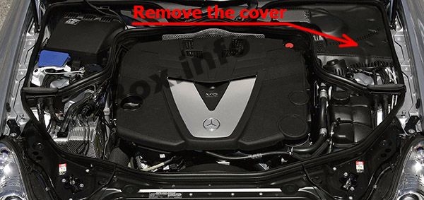
Fuse Box Diagrams – Detailed illustrations showing the arrangement of fuses, relays, and circuit breakers.
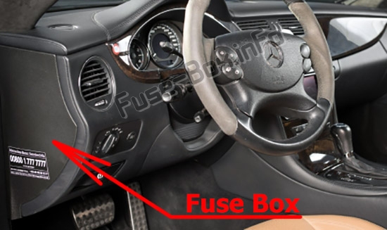
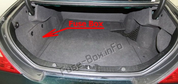
Fuse Panel Locations – Information on where to find the fuse panels inside your vehicle, such as in the cabin, engine bay, and luggage compartment.
Fuse Assignments – A complete breakdown of what each fuse and relay controls, helping with electrical diagnostics and maintenance.
Whether you’re troubleshooting an electrical issue, replacing a blown fuse, or simply getting familiar with your CLS’s electrical system, this guide offers everything you need to keep your vehicle’s systems running smoothly.
Keep your Mercedes-Benz CLS-Class (C219, 2003–2010) in top condition with this essential fuse box, fuse panel, and relay reference guide.
The cigar lighter (power outlet) fuses in the Mercedes-Benz CLS-Class are:
Front passenger partially-adjustment switch Driver partially-electric seat adjustment switch (as of 2007) Driver-side front seat adjustment control unit, with memory
30
2
Driver partially-electric seat adjustment switch Front passenger partially-electric seat adjustment switch (as of 2007) Passenger-side front seat adjustment control unit with memory
30
3
TPM [RDK] (tire pressure monitor) control unit PTS (Parktronic) control unit Navigation processor TV combination tuner (analog/digital)
7.5
4
Except engine 156.983 (CLS 55 AMG) and engine 272.985 : The fuel pump is fused via the fuel pump relay
20
4
Valid for engine 113.990 (CLS 55 AMG): The charge air cooler circulation pump is fused via the charge air cooler circulation pump relay
7.5
5
Spare relay 2
–
6
Audio gateway control unit
40
7
Rear wiper relay
15
8
Left antenna amplifier module Alarm horn Alarm signal horn with additional battery ATA [EDW] inclination sensor
Valid for M156, M272, M273: ME-SFI [ME] control unit Rear SAM control unit with fuse and relay module Valid for M642: CDI control unit Rear SAM control unit with fuse and relay module Valid for M113: ME-SFI [ME] control unit Rear SAM control unit with fuse and relay module Fuel pump relay Air injection relay
15
44
Valid for M642: CDI control unit
15
45
AIRmatic with ADS control unit
7.5
46
Automatic 5-speed transmission (NAG): ETC [EGS] control unit 7-speed automatic transmission: Electric controller unit (VGS)
7.5
47
ESP control unit
5
48
Restraint systems control unit
7.5
49
Left front reversible emergency tensioning retractor (as of 2007) Right front reversible emergency tensioning retractor (as of 2007) Restraint systems control unit (up to 2007) Front passenger seat occupied and child seat recognition sensor (up to 2007) NECK-PRO head restraints relay (2006)
7.5
50
VICS power supply separation point
5
51
–
5
52
Glove compartment illumination with switch Instrument cluster Rotary light switch Bi-xenon headlamp unit: Headlamp range adjustment control unit
7.5
53a
Fanfare horn relay
15
53b
Fanfare horn relay
15
54a
Illuminated cigar lighter
15
54b
Illuminated cigar lighter
15
55
VICS power supply separation point
7.5
56
Wiper motor
40
57
Valid for M156, M272, M273: ME-SFI [ME] control unit Rear SAM control unit with fuse and relay module Valid for engine M642: CDI control unit Rear SAM control unit with fuse and relay module
25
58
Purge control valve (up to 2007) Valid for engine 272: AAC with integrated control additional fan motor (up to 2007) USA version: Activated charcoal canister shutoff valve (up to 2007) Activated charcoal filter shutoff valve (up to 2007) Valid for engine 642: CDI control unit (2006) Valid for engine M113, M156, M272, M273: Cylinder 1 ignition coil Cylinder 2 ignition coil Cylinder 3 ignition coil Cylinder 4 ignition coil Cylinder 5 ignition coil Cylinder 6 ignition coil Cylinder 7 ignition coil Cylinder 8 ignition coil Valid for engine M113: Left O2 sensor downstream TWC [KAT] Right O2 sensor downstream TWC [KAT]
15
59
Starter relay
15
60
Valid for engine 113.990 (CLS 55 AMG), 156.983 (CLS 63 AMG): Oil cooler fan
10
61
Electric air pump
40
62
Backup relay
30
63
–
15
64
Rotary light switch Comfort automatic air conditioning control and operating unit Instrument cluster (up to 2007) AAC [KLA] control and operating unit (up to 2007)
7.5
65
EIS [EZS] control unit Electric steering lock control unit
20
66
Valid for left-hand drive vehicles: Right front lamp unit Valid for right-hand drive vehicles: Left front lamp unit Bi-xenon headlamp unit: HRA power module
7.5
67
Stop light switch
10
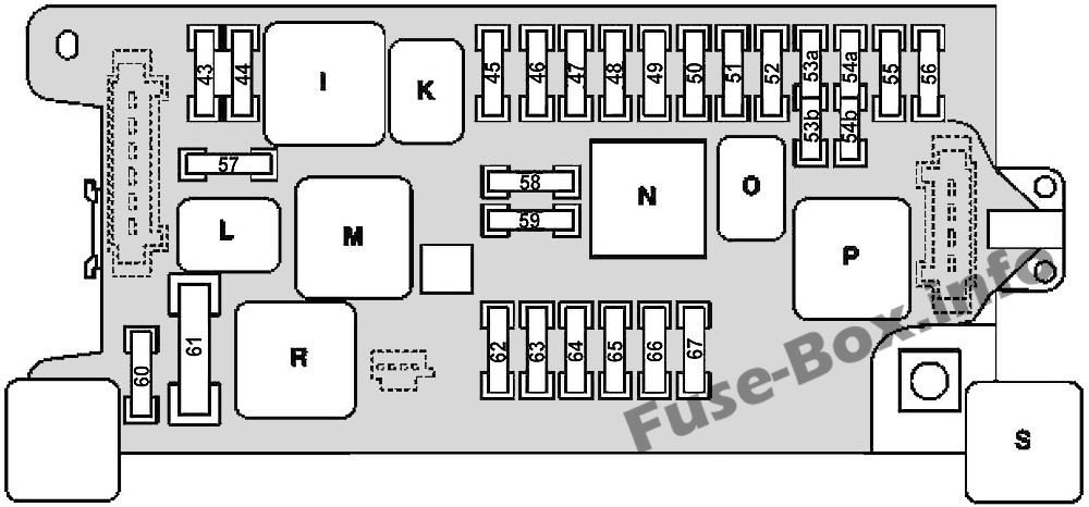
Relays
I
Terminal 87 relay, engine
K
Terminal 87 relay, chassis
L
Starter relay
M
Backup relay
N
Terminal 15 relay
O
Fanfare horn relay
P
Terminal 15R relay
R
Air pump relay (except engine 113.990 (CLS 55 AMG) and 156.983 (CLS 63 AMG)) Oil cooler fan relay (only engine 113.990 (CLS 55 AMG) and 156.983 (CLS 63 AMG))
S
AIRmatic relay (semi-active air suspension)
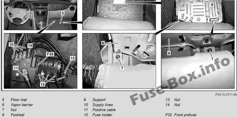
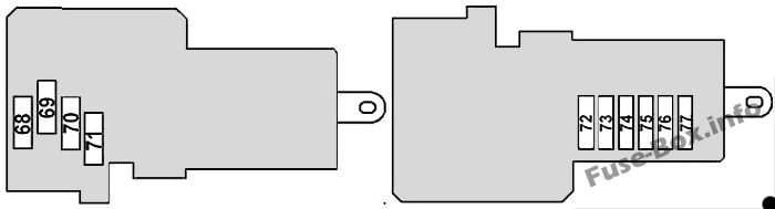
Front Pre-Fuse Box
Front Pre-Fuse Box
Fuse Data
Full access is available to registered users — log in or register.
SBC hydraulic unit (up to 31.5.06) ESP control unit (as of 1.6.06)
50
73
SBC hydraulic unit (up to 31.5.06) ESP control unit (as of 1.6.06)
40
74
AIRmatic relay
40
75
Right SAM control unit
40
76
Right front reversible emergency tensioning retractor (as of 1.6.06)
40
77
Heating systems recirculation unit
40
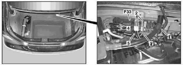
Rear Pre-fuse Box
Remove/install:
Disconnect battery ground cable Unclip latching hook (1) and remove rear prefuse box (F33) Unclip fuse holder (2) at the rear prefuse box(F33) Detach electrical connector (3) on the rear prefuse box (F33) Detach supply lines (red) (4) on the rear prefuse box (F33), mark and put the supply line (red) (4) to one side Unscrew positive lead (black) (6) on the rear prefuse box (F33) and remove positive lead (black) (6)
Install in the reverse order
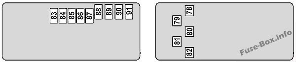
Rear Pre-fuse Box
Fuse Data
Full access is available to registered users — log in or register.
Driver-side SAM control unit with fuse and relay module
200
79
Rear SAM control unit with fuse and relay module
200
80
Driver SAMcontrol unit with fuse and relay module
150
81
Interior fuse box
150
82
AMG vehicles: FP fuse (F82A), Air injection fuse (F82B)
150
F82A
Left fuel pump control unit Right fuel pump control unit
30
F82B
Air injection relay
40
83
–
30
84
Battery sensor (as of 2007) Battery control unit (up to 2007)
5
85
Voice control system (VCS [SBS]) control unit Universal Portable CTEL Interface (UPCI [UHI]) control unit Japan version: GPS box control unit Microphone array control unit USA version: CTEL [TEL] compensator, data E-net compensator
5
86
USA version: SDAR control unit (up to 2007)
5
87
Pneumatic pump for dynamic seat control
30
88
TLC [HDS] control unit
30
89
–
40
90
Left front reversible emergency tensioning retractor (as of 2007)
40
91
Valid with engine 272.985: Fuel pump control unit (as of 2007)
")