The Mercedes-Benz GLC (GLC-Class; X253, C253) , available from 2016 to 2022 , is a compact luxury crossover that delivers a perfect balance of performance, elegance, and advanced technology . As the successor to the GLK-Class a refined interior, powerful engine options, and innovative driver assistance features , making it a top choice in the luxury SUV segment .
In this article, you will find fuse box diagrams for the Mercedes-Benz GLC-Class , covering models GLC250, GLC300, GLC350, GLC43 AMG, and GLC63 AMG for the years 2016, 2017, 2018, 2019, 2020, 2021, and 2022 . These diagrams provide crucial insights into the fuse layout , helping vehicle owners, mechanics, and technicians locate and understand the function of each fuse and relay .
What’s Included:
Fuse Box Diagrams – Clear and detailed visuals to help identify fuses, relays, and circuit breakers .Fuse Panel Locations – Step-by-step guidance on where to find the fuse panels inside the Mercedes-Benz GLC-Class.Fuse Assignments – Comprehensive descriptions of each fuse and relay function for accurate diagnostics and troubleshooting.
Whether you’re searching for the fuse panel layout , replacing a blown fuse , or diagnosing an electrical issue , this guide is an essential resource. It ensures that your Mercedes-Benz GLC-Class’s electrical system remains functional and reliable for daily commuting, long road trips, and premium driving experiences .
Keep your Mercedes-Benz GLC-Class (2016–2022) in peak condition with this detailed fuse box, fuse panel, and relay guide!
The cigar lighter/power outlet fuses (all are located in the Luggage Compartment Fuse Box ) in the Mercedes-Benz GLC are:
Fuse №445 : Luggage Compartment SocketFuse №446 : Front Cigarette Lighter, Interior Power OutletFuse №447 : Right Rear Center Console Socket
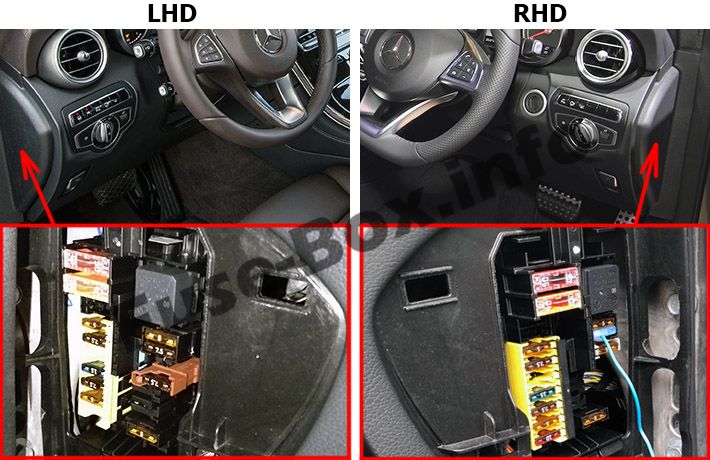
The fuse box is located on the driver’s side edge of the instrument panel, behind the cover.
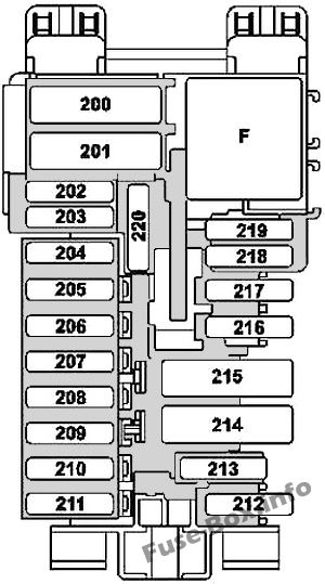
Assignment of the fuses in the instrument panel
Fuse Data
Full access is available to registered users — log in or register.
Log in or register
№ Fused component Amp 200 Front SAM control unit 50 201 Front SAM control unit 40 202 Alarm siren 5 203 Valid with transmission 716: Electric steering lock control unit 20 204 Diagnostic connector 5 205 Electronic ignition lock control unit 7.5 206 Analog clock 5 207 Climate control control unit 15 208 Instrument cluster 7.5 209 Climate control operating unit 5 210 Steering column tube module control unit 10 211 Spare 25 212 Spare 5 213 Electronic Stability Program control unit 5 214 Spare 30 215 Spare – 216 Glove compartment lamp 7.5 217 Japan version: Dedicated Short-Range Communications control unit 5 218 Supplemental Restraint System control unit 7.5 219 Weight sensing system (WSS) control unit 5 220 Spare – Relay F Relay, circuit 15R
This content requires JavaScript and a valid membership to view.
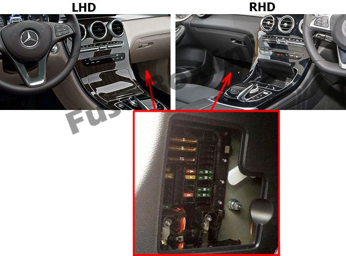
Fuse Box in the Front-Passenger Footwell
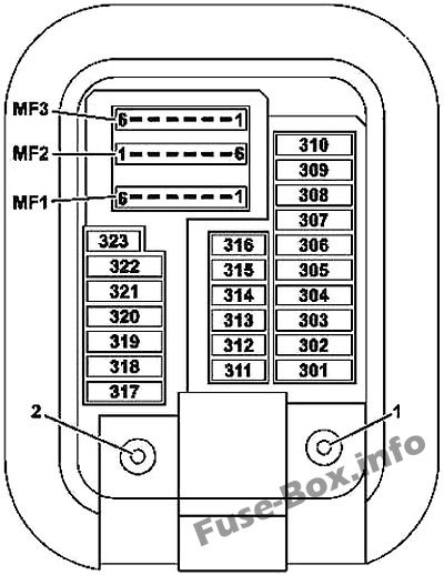
Assignment of the fuses in the Front-Passenger Footwell
Fuse Data
Full access is available to registered users — log in or register.
Log in or register
№ Fused component Amp 301 Hybrid: Pyrofuse via high-voltage disconnect device 5 302 Right front door control unit 30 303 Left rear door control unit 30 304 Valid for transmission 722: Intelligent servo module for DIRECT SELECT (A80) 20 305 Driver seat control unit 30 306 Front passenger seat control unit 30 307 Spare – 308 USA version: Electric Brake Control electrical connector 30 309 Emergency call system control unit 10 309 HERMES control unit 5 310 Spare – 311 Booster blower electronic blower regulator 10 312 Overhead control panel control unit 10 313 Hybrid: DC/DC converter control unit 10 314 Spare – 315 Powertrain control unit 5 316 Supplemental Restraint System control unit 7.5 317 Panoramic sliding sunroof control module 30 318 Stationary heater control unit 20 319 Hybrid: High-voltage PTC heater 5 320 AIR BODY CONTROL control unit 15 321 Japan version: Dedicated Short-Range Communications control unit 5 322 Head unit 20 323 Parking system control unit 5 MF1/1 Audio/COMAND display 7.5 MF1/2 Stereo multifunction camera 7.5 MF1/3 Rain/light sensor with additional functions 7.5 MF1/4 Driver seat control unit 7.5 MF1/5 Front passenger seat control unit 7.5 MF1/6 Steering column tube module control unit 7.5 MF2/1 Left front reversible emergency tensioning retractor 5 MF2/2 Audio/COMAND control panel 5 MF2/3 Right front reversible emergency tensioning retractor 5 MF2/4 Heads-up display 5 MF2/5 Multimedia connection unit 5 MF2/6 Hybrid: Electrical refrigerant compressor 5 MF3/1 Feedback line, terminal 30g, front SAM control unit 5 MF3/2 Radar sensors control unit 5 MF3/3 Spare – MF3/4 Driver side instrument panel button group 5 MF3/5 Rear air conditioning operating unit 5 MF3/6 Tire pressure monitor control unit
This content requires JavaScript and a valid membership to view.
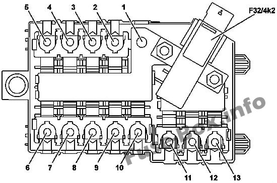
Interior Pre-Fuse Box
Fuse Data
Full access is available to registered users — log in or register.
Log in or register
№ Fused component Amp 1 Engine compartment prefuse box – 2 Hybrid: Additional battery relay for ECO start/stop function 150 3 Blower regulator 40 4 Spare – 5 Valid for diesel engine: PTC heater booster 150 6 Right A-pillar fuse box 80 7 Rear fuse and relay module 150 8 Spare – 9 Spare – 10 Valid for transmission 725 (except GLC 350 e 4Matic): Fully integrated transmission control unit 60 10 GLC 350 e 4Matic: Fully integrated transmission control unit 100 11 Spare – 12 Rear fuse and relay module 40 13 Right A-pillar fuse box 50 F32/4k2 Quiescent current cutout relay
This content requires JavaScript and a valid membership to view.
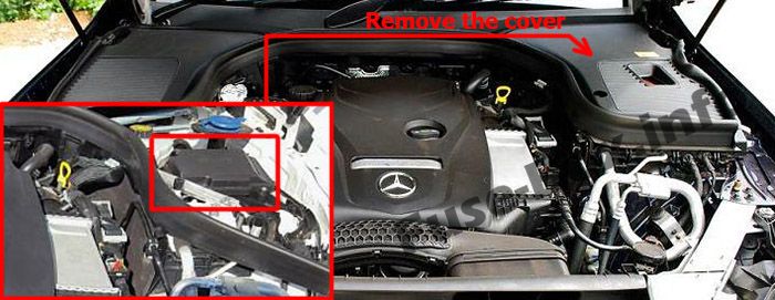
The fuse box is located in the engine compartment (left-side), under the cover.
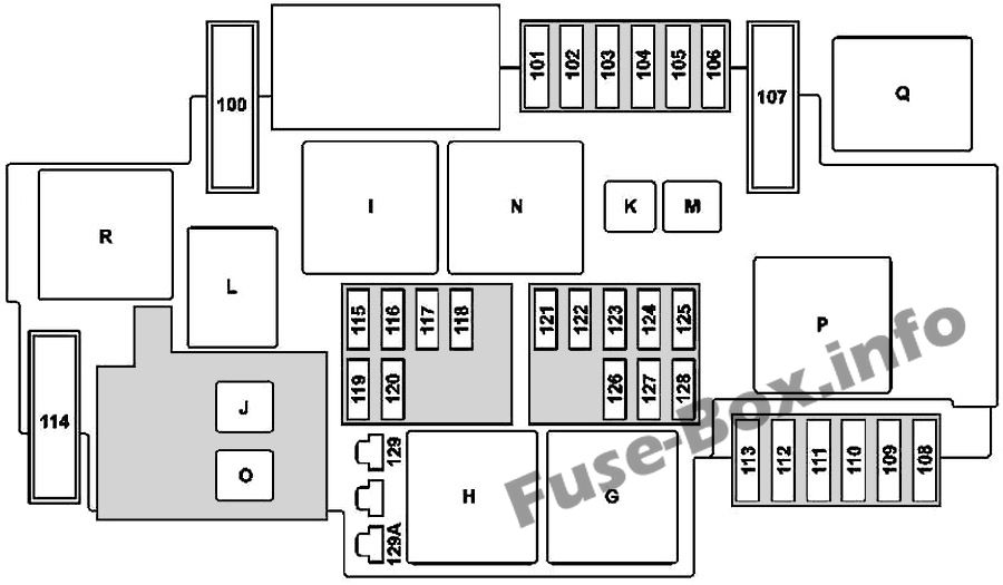
Assignment of the fuses and relay in the engine compartment
Fuse Data
Full access is available to registered users — log in or register.
Log in or register
№ Fused component Amp 100 Hybrid: Vacuum pump 40 101 Connector sleeve, circuit 87/2 15 102 Connector sleeve, circuit 87/1 20 103 Connector sleeve, circuit 87/4 15 104 Connector sleeve, circuit 87/3 15 105 Valid for transmission 722.9 (except 722.930): Automatic transmission fluid auxiliary oil pump control unit 15 106 Spare – 107 Valid with engine 274.9: Electric coolant pump 60 108 Static LED headlamp: Right front lamp unit 20 109 Wiper motor 30 110 Static LED headlamp: Left front lamp unit 20 111 Starter 30 112 Hybrid: Accelerator pedal sensor 15 113 Spare – 114 AIR BODY CONTROL compressor 40 115 Left horn and right horn 15 116 Spare – 117 Spare – 118 Hybrid: Electronic Stability Program control unit 5 119 Circuit 87 C2 connector sleeve 15 120 Circuit 87 C1 connector sleeve 5 121 Electronic Stability Program control unit 5 122 CPC relay 5 123 Spare – 124 Spare – 125 Front SAM control unit 5 126 Powertrain control unit 5 127 Hybrid: Voltage dip limiter 5 128 Left front lamp unit and exterior lights switch 5 129 Hybrid: Starter circuit 50 relay 30 129A Hybrid: Starter circuit 50 relay 30 Relay G Engine compartment circuit 15 relay H Starter circuit 50 relay I Hybrid: Vacuum pump relay (+) J CPC relay K Valid for transmission 722.9 (except 722.930): Oil pump relay L Horn relay M Wiper park position heater relay N Circuit 87M relay O Hybrid: Starter circuit 15 relay P Valid with engine 274.9: Coolant pump relay Q Hybrid: Vacuum pump relay (-) R AIR BODY CONTROL relay
This content requires JavaScript and a valid membership to view.
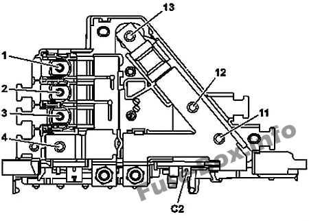
Engine Pre-Fuse Box
Fuse Data
Full access is available to registered users — log in or register.
Log in or register
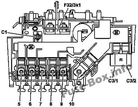
№ Fused component A 1 Spare – 2 Valid for diesel engine: Glow output stage 100 3 Engine fuse and relay module 60 4 On-board electrical system battery connection – 5 Engine fuse and relay module 150 6 Left fuse and relay module 125 7 Fan motor (600 W / 850 W) 80 8 Electrical power steering control unit 125 9 Fan motor (1000 W) 150 10 Vehicle interior prefuse box 200 11 Spare – 12 Hybrid: Power electronics control unit – 13 Alternator 400 C1 Hybrid: Decoupling relay – C2 Hybrid: Circuit 31 – C3/1 Electronic Stability Program control unit 40 C3/2 Electronic Stability Program control unit 60
This content requires JavaScript and a valid membership to view.
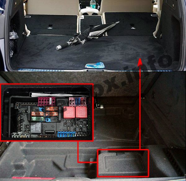
The fuse box is located in the luggage compartment (on the right-side), under the floor lining and under the cover.
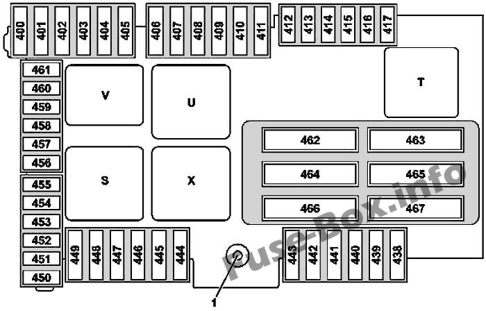
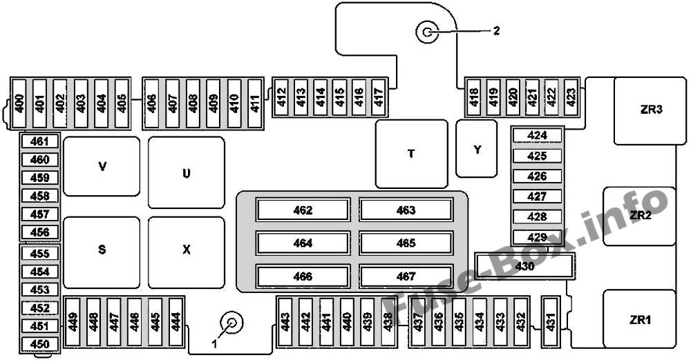
Assignment of the fuses and relay in the luggage compartment
Fuse Data
Full access is available to registered users — log in or register.
Log in or register
№ Fused component Amp 1 Terminal 30 “E1” feed 2 Terminal 30g “E2” feed 400 BlueTEC: AdBlue control unit 25 401 BlueTEC: AdBlue control unit 15 402 BlueTEC: AdBlue control unit 20 403 Valid up to 30.11.2015: Front passenger seat partially electric seat adjustment switch 30 403 Valid as of 01.12.2015: Front passenger seat partially electric seat adjustment switch 25 404 Valid up to 30.11.2015: Driver seat partially electric seat adjustment switch 30 404 Valid as of 01.12.2015: Driver seat partially electric seat adjustment switch 25 405 Spare – 406 Left front door control unit 30 407 Spare – 408 Right rear door control unit 30 409 Spare – 410 Stationary heater radio remote control receiver 5 411 Left front reversible emergency tensioning retractor 30 412 Hybrid: Battery management system control unit 7.5 413 Trunk lid control control unit 5 414 Tuner unit 5 415 Camera cover control unit 5 416 Cellular telephone system antenna amplifier/compensator 7.5 417 360° camera control unit 5 418 Rear seat heater control unit 5 419 Front passenger seat lumbar support adjustment control unit 5 420 Driver seat lumbar support adjustment control unit 5 421 Spare – 422 Spare – 423 Sound system amplifier control unit 5 424 AIR BODY CONTROL Plus control unit 15 425 Spare – 426 Spare – 427 Spare – 428 Spare – 429 Spare – 430 Spare – 431 Special-purpose vehicle multifunction control unit 25 432 Special-purpose vehicle multifunction control unit 25 433 Trailer recognition control unit 20 434 Trailer recognition control unit 30 435 Trailer recognition control unit 25 436 Trailer recognition control unit 15 437 Trailer recognition control unit 25 438 DC/AC converter control unit 30 439 Spare – 440 Rear seat heater control unit 30 441 AIRSCARF control unit 30 442 Fuel system control unit 25 443 Right front reversible emergency tensioning retractor 30 444 Tablet PC electrical connector 15 445 Luggage compartment socket 15 446 Front cigarette lighter with ashtray illumination 15 447 Right rear center console socket 12V 15 448 Valid for transmission 722, 725: Park pawl capacitor 10 449 Valid for engine 626: Fuel filter element with integrated heater 5 450 Rear SAM control unit 5 451 Fuel system control unit 5 452 Integrated outer right rear bumper radar sensor 5 453 Left front bumper radar sensor 5 454 Valid for transmission 722: Fully integrated transmission control unit 7.5 454 BlueTEC: AdBlue control unit 5 455 DC/AC converter control unit 5 456 Front long-range radar sensor 5 457 Hybrid: 5 458 Rear switching module 5 459 Hybrid: Charger 5 460 KEYLESS-GO control unit 10 461 FM 1, AM, CL [ZV] and KEYLESS-GO antenna amplifier 5 462 Sound system amplifier control unit 40 463 Rear window heater via rear window interference suppression capacitor 30 464 Trunk lid control control unit 40 465 Rear SAM control unit 40 466 Rear SAM control unit 40 467 Valid for engine 626: Fuel filter element with integrated heater 40 Relay S Vehicle interior circuit 15 relay T Rear window heater relay U 2nd seat row cup holder and sockets relay V BlueTEC: AdBlue relay X 1 st seat row/trunk refrigerator box and sockets relay Y Spare relay ZR1 Valid for engine 626: Fuel filter heater relay ZR2 Reserve relay ZR3 Reserve relay
This content requires JavaScript and a valid membership to view.