View Mercedes-Benz M-Class (ML) fuse box diagrams for 2012–2015 models with fuse locations, panel layouts, and detailed electrical information for all variants. This article covers the third-generation Mercedes-Benz M-Class (ML) (Model Code: W166), available from 2012 to 2015, and includes fuse box diagrams for Mercedes-Benz ML350, ML400, ML500, ML63 and ML250 CDI (2012, 2013, 2014 and 2015), along with details about the location of the fuse panels inside the vehicle and a clear explanation of the assignment of each fuse (fuse layout).
NEED A REPLACEMENT?
Looking for the right fuse or relay?
Search common fuse types, fuse kits and relay options for your vehicle.
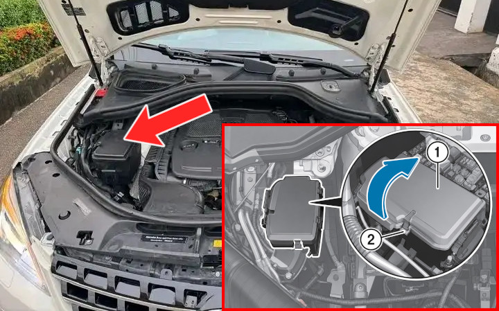
The fuse box is situated in the engine compartment on the passenger side. To access the fuses, open clamps (2), lift cover (1) in the direction indicated by the arrow, and remove it.
Fuse Box Diagram
Fuses
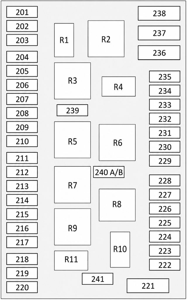
Assignment of the fuses in the engine compartment
Fuse Data
Full access is available to registered users — log in or register.
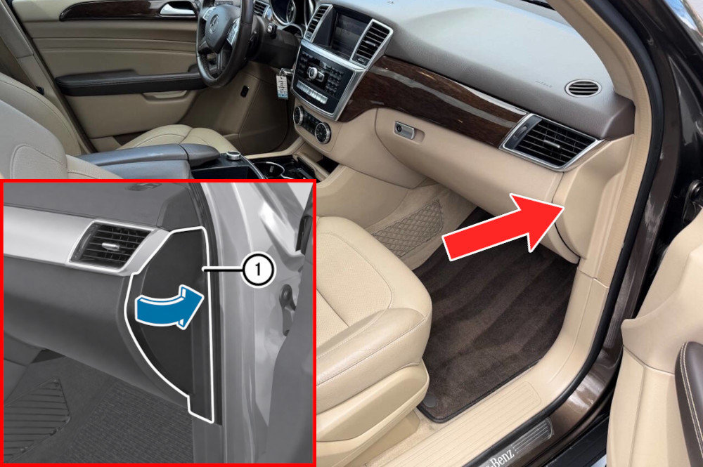
The fuse box is situated in the passenger compartment at the edge of the dashboard on the passenger side. To access the fuses, pull cover (1) outward in the direction indicated by the arrow, then remove it.
Fuse Box Diagram
Fuses
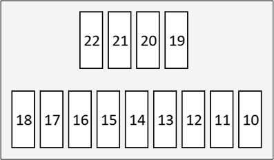
Assignment of the fuses in the passenger compartment (Dashboard)
Fuse Data
Full access is available to registered users — log in or register.
The fuse box is positioned beneath the front passenger seat, in the compartment beside the battery. For easier access, slide the seat fully forward and fold it down.
Fuse Box Diagram
Fuses
Assignment of the fuses in the battery compartment
Fuse Data
Full access is available to registered users — log in or register.
Control unit for passenger restraint system (Supplemental Restraint System)
60
7.5A
Ceiling control box
62
15A
AIRMATIC control unit
63
20A
Panoramic sliding sunroof control module, Sliding sunroof control module
64
30A
Air pump for multi-contour seat
65
30A
Fuse box, terminal 30g, front panel
67
30A
Electric parking brake control unit
68
30A
Electric parking brake control unit
MF1-1
Audio module/COMAND system control panel
MF1-2
Bottom Control Panel, Off-road driving mode control panel
MF1-3
Parking assistance control unit
MF1-4
Control unit for electronic stability control
MF1-5
SAM control unit
MF1-6
Speaker amplifier control unit
MF2-1
HBF control unit
MF2-2
Tire pressure monitoring control unit
MF2-3
Digital audio broadcasting control unit, Satellite Digital Audio Radio (SDAR) control unit
MF2-4
Multi-function camera
MF2-5
Multimedia interface control unit
MF2-6
Rear View Camera, 360° camera control box
MF3-1
Rear left display
MF3-2
Rear right display
MF3-3
TV tuner (analog/digital), Digital TV tuner
MF3-4
DVD player
MF3-5
Control unit for video and radar sensors
Rear Compartment
Fuse Box Location
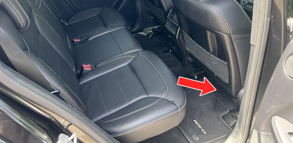
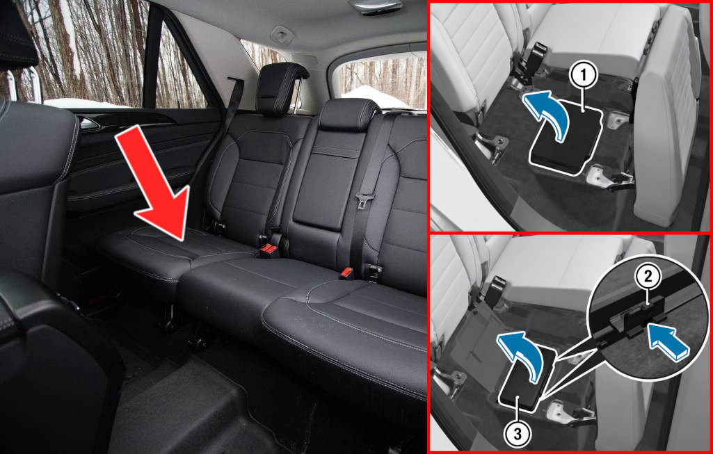
It is positioned beneath the right rear bench seat. Fold the right-hand rear bench seat forward, then lift and fold back the carpet (1) in the direction shown by the arrow. Press the clamps (2) in the arrow’s direction to release them. Fold the cover (3) upward as indicated and remove it.
Fuse Box Diagram
Fuses
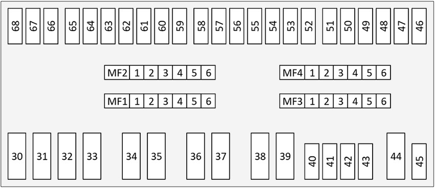
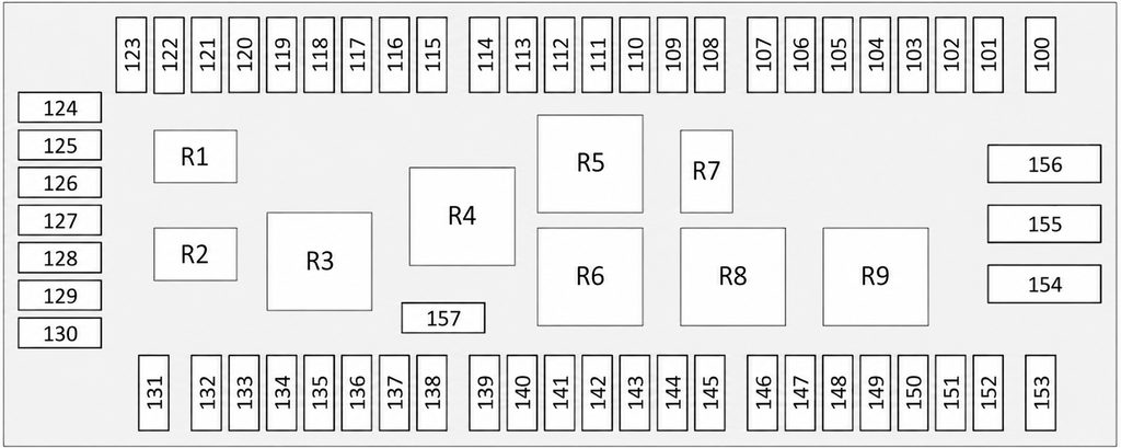
Assignment of the fuses in the rear compartment
Fuse Data
Full access is available to registered users — log in or register.
Audio module, COMAND control module, Electrical plug connection for external navigation
101
20A
Trailer detection control unit
102
7.5A
Driver’s seat control unit
103
7.5A
Front passenger seat control unit
104
5A
Antenna Amplifier / Mobile Phone Compensator, Bluetooth module
105
5A
Holder for navigation module
106
5A
Tailgate control unit
107
10A
Release module, 2nd row of seats, left; Release module, 2nd row of seats, right
108
—
–
109
—
–
110
5A
AdBlue control unit
111
15A
Trailer socket
112
5A
Fuel pump control unit
113
5A
Electric parking brake control unit
114
5A
Switch for exterior lighting
115
5A
Trailer detection control unit
116
5A
Termination of terminal 87 of the radar control unit, Collision Prevention Assist control module
117
5A
Night vision control unit
118
—
–
119
5A
Transfer case control unit
120
5A
Fuel quality sensor, Digital tachograph control unit
121
—
–
122
—
–
123
—
–
124
30A
Electrical plug connection for the Electric Brake Control function
125
—
–
126
15A
Trailer recognition control unit
127
30A
Driver seat control unit
128
20A
Trailer recognition control unit
129
30A
Front passenger seat control unit
130
20A
Trailer recognition control unit
131
—
–
132
25A
Fuel pump control unit
133
5A
Radio remote control receiver for auxiliary heater
134
5A
Seat occupied recognition pressure sensor, Occupancy recognition and AKSE, front passenger seat
135
5A
Glove box light
136
7.5A
Control unit for passenger restraint system (Supplemental Restraint System)
137
5A
Electric fuse preparation for installation of the Electronic Toll Collection system, Electronic equipment rear view camera, Electrical plug connection for external navigation
138
15A
Active roll stabilization control unit
139
—
–
140
7.5A
AdBlue control unit
141
15A
AdBlue control unit
142
20A
AdBlue control unit
143
—
–
144
—
–
145
7.5A
Cup holder
146
30A
Rear window notch filter
147
30A
Audio module, COMAND control module
148
15A
Cigarette lighter heating element, Detachable cup holder connection
149
5A
Socket 115 V
150
20A
Socket in trunk
151
20A
Socket, 2nd seat row, left; Socket in the 2nd row of seats on the right
152
30A
Rear compartment systems control unit
153
25A
AC/DC converter control unit
154
40A
Tailgate control unit
155
—
–
156
—
–
157
15A
Tailgate wiper motor
Relays
Assignment of the relays in the rear compartment
Fuse Data
Full access is available to registered users — log in or register.