The second-generation Mercedes-Benz SLK-Class (R171), produced from 2004 to 2010, is a luxury retractable hardtop roadster known for its sporty design, high-performance engine options, and refined driving dynamics. Featuring improved aerodynamics, enhanced safety features, and advanced technology, the SLK R171 continued the tradition of stylish, open-top driving with Mercedes-Benz engineering excellence.
In this article, you will find fuse box diagrams for the Mercedes-Benz SLK-Class, covering models SLK200, SLK280, SLK300, SLK350, and SLK55 AMG for the years 2004, 2005, 2006, 2007, 2008, 2009, and 2010. These diagrams provide essential insights into the fuse layout, helping vehicle owners, mechanics, and technicians locate and understand the function of each fuse and relay.
What’s Included:
Fuse Box Diagrams – Clear and detailed visuals to help identify fuses, relays, and circuit breakers.
Fuse Panel Locations – Step-by-step guidance on where to find the fuse panels inside the Mercedes-Benz SLK.
Fuse Assignments – Comprehensive descriptions of each fuse and relay function for accurate diagnostics and troubleshooting.
Whether you’re searching for the fuse panel layout, replacing a blown fuse, or diagnosing an electrical issue, this guide is an essential resource. It ensures that your Mercedes-Benz SLK’s electrical system remains functional and reliable for sporty drives, weekend road trips, and top-down cruising.
Keep your Mercedes-Benz SLK-Class (2004–2010) in peak condition with this detailed fuse box, fuse panel, and relay guide!
The cigar lighter (power outlet) fuse in the Mercedes-Benz SLK-Class is:
fuse №47, located in the Engine Compartment Fuse Box.
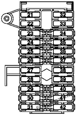
Right rear power window motor (up to 2008) Soft top operation control unit (as of 2009)
25
33
LHD: Steering column module
5
34
Steering wheel adjustment (up to 2008) Driver-side front seat adjustment control unit, with memory (as of 2009)
30
35
Front passenger seat adjustment (up to 2008) Passenger-side front seat adjustment control unit with memory (as of 2009)
30
36
EIS [EZS] control unit Electric steering lock control unit
15
37
Upper control panel control unit Automatic air conditioning (KLA) or comfort automatic air conditioning (C-AAC) Mirror adjustment (up to 2008) Vario roof (VD) control (up to 2008) Duovalve (up to 2008) Mirror folding-in (up to 2008) HEAT control and operating unit (as of 2009) Comfort AAC [KLA] control and operating unit (as of 2009)
7.5
38
Soft top mechanism hydraulic unit
40
39
Left rear power window motor (up to 2008) Soft top operation control unit (as of 2009)
25
40
Data link connector (1.3) (up to 2008) Central gateway control unit
5
41
Radio systems (up to 2008) Navigation system (up to 2008) Emergency call system control unit (as of 2009) Digital Audio Broadcasting control unit (as of 2009) SDAR control unit (as of 2009)
5
42
RHD: Steering column module
5
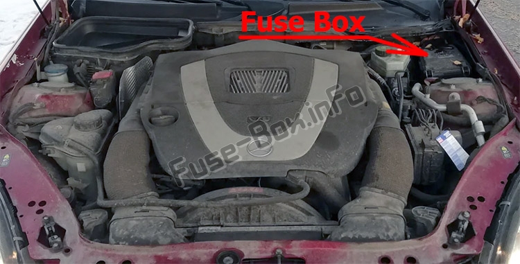
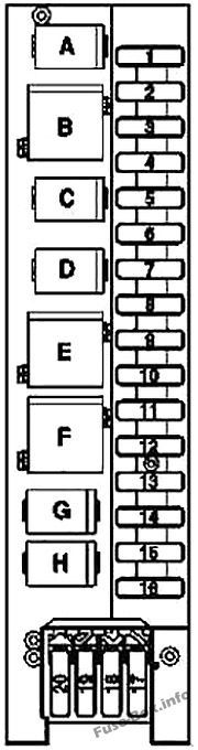
Engine Compartment Fuse Box
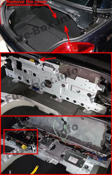
Fuse box location
It is located in the engine compartment, under the cover.
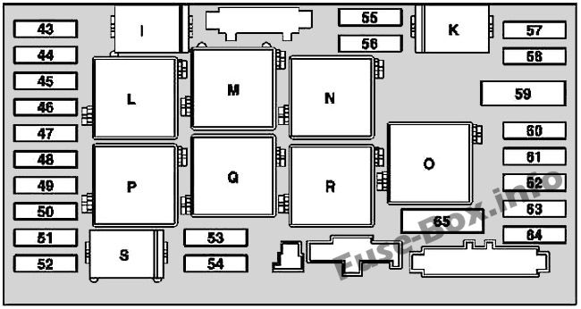
Fuse box diagram
Assignment of the fuses and relay in the engine compartment
Fuse Data
Full access is available to registered users — log in or register.
Glove compartment illumination with switch Stowage compartment illumination between backrests (as of 2009) Armrest stowage compartment lighting (as of 2009) C-AAC [K-KIA] multifunction sensor
5
45
ARMADA airbag control unit (up to 2008) Airbag indicator and warning lamp (up to 2008) Restraint systems control unit (as of 2009) Front passenger seat occupied and child seat recognition sensor (as of 2009; USA) Weight Sensing System (WSS) control unit (as of 2009; USA)
7.5
46
Wiper system (WSA)
40
47
Cigar lighter with ashtray illumination Interior socket Radio systems (up to 2008)
15
48
Not used
–
49
ARMADA airbag control unit (up to 2008) Airbag indicator and warning lamp (up to 2008) Restraint systems control unit (as of 2009)
7.5
50
Switch and controls illumination on exterior lamp switch
5
51
Instrument cluster (up to 2008) Headlamp range adjustment (HRA) (up to 2008) Electric suction-type fan for engine/AC (up to 2008)
5
51
HRA power module (as of 2009) Valid with engine 113.989 (SLK55 AMG): Control unit box blower motor (as of 2009)
7,5
52
Starter
15
53
Engine control circuit 87/M1 (up to 2008) Rear SAM control unit with fuse and relay module (as of 2009) Starter relay (as of 2009) Valid for engines 271, 272: ME-SFI [ME] control unit (as of 2009) Valid with engine 113.989 (SLK 55 AMG): ME-SFI [ME] control unit (as of 2009) Valid with engine 113.989 (SLK 55 AMG): Circuit 87 M1e connector sleeve (as of 2009) Valid for engine 272: Circuit 87 M1e connector sleeve (as of 2009)
25
54
Engine control, circuit 87/M2 (up to 2008) AAC with integrated control additional fan motor (as of 2009) Valid with engine 113.989 (SLK55 AMG), 272: Air pump relay (as of 2009)
15
55
Headlamp range adjustment (HRA) Backup lamp switch (up to 2008) Valid for transmission 722:Electric control unit (VGS) (up to 2008) Valid for transmission 722: Electronic selector lever module control unit (as of 2009) Valid for transmission 722.6: ETC [EGS] control unit (as of 2009)
7.5
56
Electronic stability program (ESP)
5
57
EIS [EZS] control unit Valid for engine 113.989 (SLK 55 AMG), 272: Engine management
5
58
Not used
–
59
ESP [Electronic Stability Program] (pump)
50
60
ESP (valve block)
40
61
Not used
–
62
Data link connector Exterior lamp switch
5
63
Exterior lamp switch
5
64
Radio systems (up to 2008) Navigation system (up to 2008)
10
65
Valid for engine 113.989 (SLK 55 AMG), 272: Electric air pump
40
Relay
I
FAN relay module (up to 2008) Fanfare horn I relay (as of 2009)
K
Circuit 87 relay, chassis
L
Wiper relay, stage 1-2
M
Circuit 15R relay
N
Backup relay
O
Valid with engine 113.989 (SLK55 AMG), engine 272: Air pump relay
P
Circuit 15 relay
Q
Wiper ON and OFF relay
R
Circuit 87 relay, engine
S
Starter relay
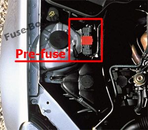
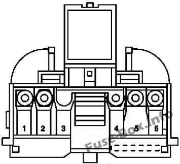
Engine Pre-Fuse Box
Fuse box location
Fuse box diagram
Fuse Data
Full access is available to registered users — log in or register.
Vehicle Information and Communication System (VICS) (Japan only) (up to 2008)
5
2
Not used
–
3
Telephone system (up to 2008) Tire pressure monitor control unit (as of 2009) Parktronic control unit (as of 2009)
7.5
4
Fuel pump assembly
20
5
Reserve 2 relay (as of 2009)
20
6
Not used
–
7
Reserve 1 relay (as of 2009)
20
8
Left antenna amplifier module, right antenna amplifier module (up to 2008), left rear bumper antenna amplifier (up to 2008) Anti-theft alarm system (ATA [EDW]) Compensator
5
9
Parktronic System (PTS) (up to 2008)
5
9
Seat heater, AIRSCARF and steering wheel heater control unit (as of 2009)
25
10
Rear window defroster
40
11
Not used
–
12
Not used
–
13
Stowage compartment illuminat (up to 2008) CDA telephone (retrofit wiring harness) (up to 2008) Lumbar pump (as of 2009) Emergency call system control unit (as of 2009) VICS+ETC voltage supply separation point (as of 2009)
5
14
Not used
–
15
Interior central locking (up to 2008) Filler cap release (up to 2008) Fuel filler flap CL [ZV] motor (as of 2009) Glove compartment CL [ZV] motor (as of 2009) CL center console compartment motor (as of 2009)
5
16
Lumbar pump (as of 2009)
7.5
17
Digital Audio Radio satellite (SDAR) (USA only) (up to 2008) Voice control system (VCS) (USA only) (up to 2008)
5
18
Seat heater, AIRSCARF and steering wheel heater control unit (as of 2009)
20
19
CD player with changer (in glove compartment) (up to 2008) Navigation system (up to 2008)
7.5
19
Seat heater, AIRSCARF and steering wheel heater control unit
20
20
Emergency call system (USA only) (up to 2008)
7.5
20
Seat heater, AIRSCARF and steering wheel heater control unit
 | 1995-2004")
 | 2011-2020")