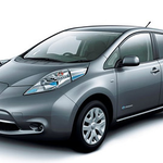
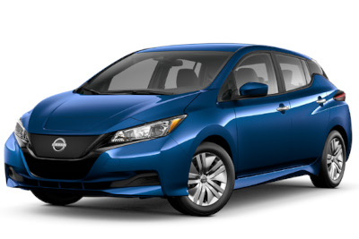
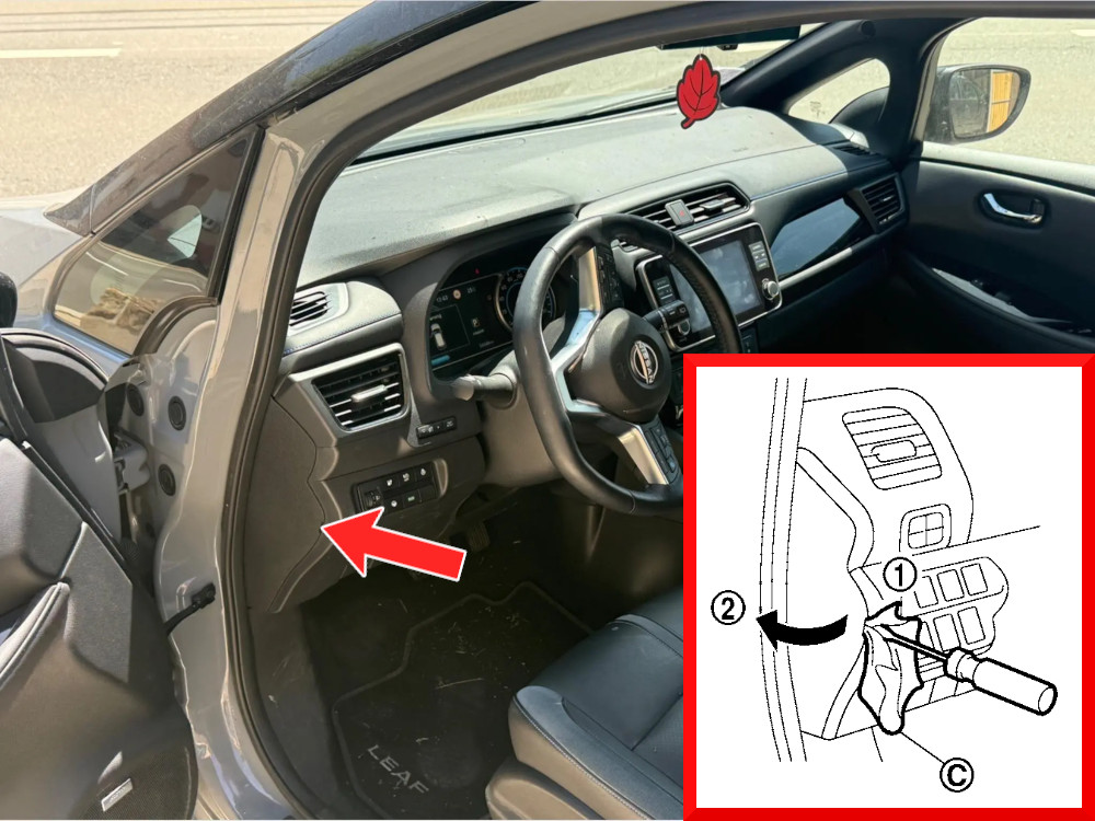
Discover Nissan Leaf fuse box diagrams for 2018–2025 models with fuse locations, panel layouts, and detailed fuse and relay assignment information for this all-electric hatchback. This article covers the second-generation Nissan Leaf (Model Code: ZE1), available from 2018, and includes fuse box diagrams for Nissan Leaf 2018, 2019, 2020, 2021, 2022, 2023, 2024 and 2025, along with details about the location of the fuse panels inside the vehicle and a clear explanation of the assignment of each fuse and relay (fuse layout).
NEED A REPLACEMENT?
Looking for the right fuse or relay?
Search common fuse types, fuse kits and relay options for your vehicle.
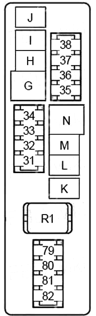
Air Conditioning (A/C) Relay (Heater Pump, Electric Compressor, Fan Relay (Coil), Mode Damper Motor, Air Mixing Damper Motor)
33
MINI
10A
F/S CHG Relay, Power Delivery Module (PDM), DC/DC, On-Board Charger
34
MINI
20A
Telematics control unit (TCU), AV control unit, audio system unit, Bluetooth control unit
35
MINI
10A
Horn Relay
36
—
—
Not Used
37
MINI
10A
Daytime running lights relay
38
MINI
10A
Brake Light Switch, Brake Lights, High Brake Light, Body Control Module (BCM), Power Intelligent Brake Control Module (EDIB), Vehicle Control Module (VCM) Lamp, Safety Monitor, Approach Sound Control Module for pedestrians (VSP)
79
MINI
15A
Daytime Running Lights (Right)
80
MINI
15A
Daytime Running Lights (Left)
81
—
—
Not Used
82
MINI
15A
Backup Brake Power Supply, Electric Drive Intelligent Brake (EDIB)
Body Control Module (BCM), Power Windows, Security Management System, Power Door Lock, Tire Pressure Monitoring System, Rear Wiper/Washer, Auxiliary Relay (Coil), Automatic Light System, Turn Signal and Hazard Lights
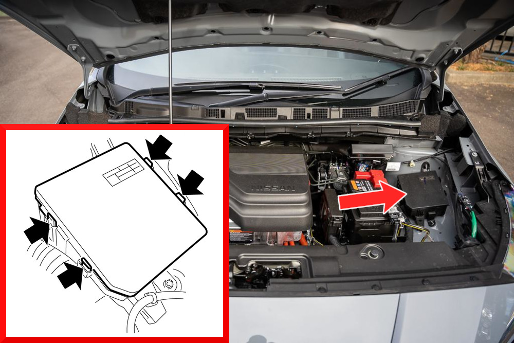
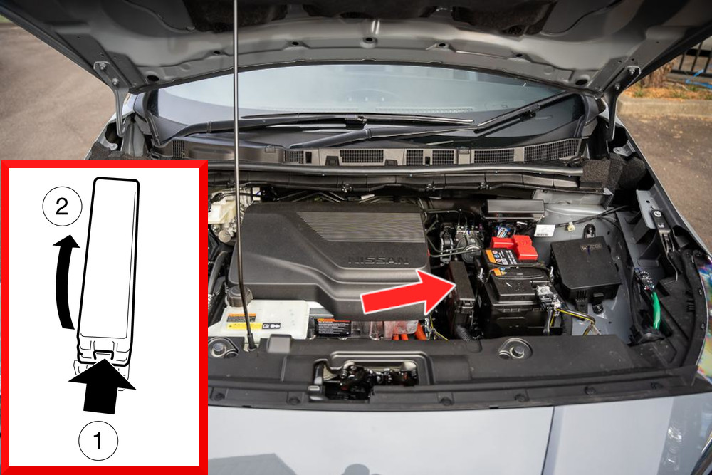
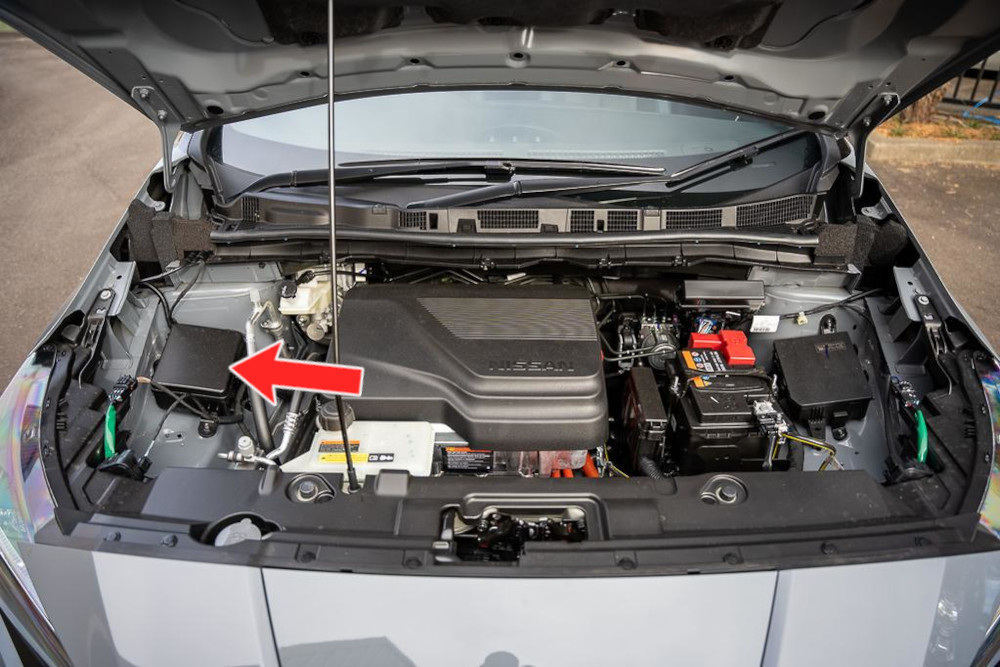
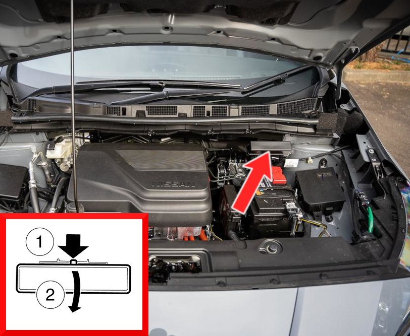
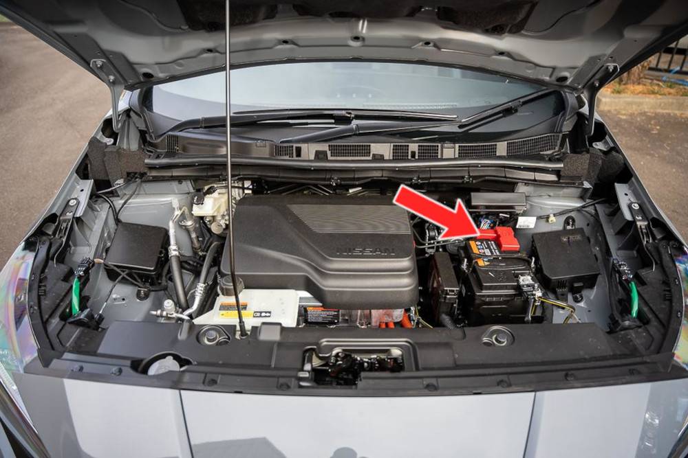
The fuse box is located on the passenger side of the engine compartment. Follow the image below to identify its exact position and locate the box more easily.
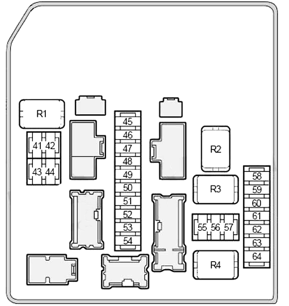
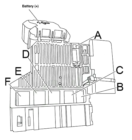
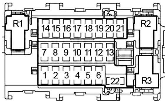
Fuse Box Diagram
Fuses
Assignment of the fuses in the engine compartment fuse box (3)
Fuse Data
Full access is available to registered users — log in or register.
Airbag Diagnostic Sensor Module, Occupant Classification System (OCS) Control Module, Passenger Airbag Off Indicator, Vehicle Sound Pedestrian (VSP) Control Module, VSP Warning Lamp, VSP Switch Off Lamp
2
MINI
10A
Combination Switch (Wiper/Washer Pump)
3
MINI
10A
Telematics Control Unit (TCU), AV Control Unit, Brake Switch/ASCD, Brake Switch, ABS Drive and Control Unit, Auto Dimming Interior Mirror, Integrated HomeLink Transmitter, Data Link Connector, Electric Motor Headlight Leveling Control Left/Right, Automatic Power A/C, Electric Parking Brake Control Module, Electronic Power Steering (EPS) Control Module, On-Board Charger, Vehicle Control Module (VCM), Bluetooth Control Module, Around View Monitor Control
4
MINI
10A
Steering angle sensor, ABS drive and control unit
5
MINI
10A
Combined Instrument, Buzzer, LED Headlight Control Module, Vehicle Sound Pedestrian (VSP) Control Module
6
—
—
Not Used
7
MINI
10A
Remote Keyless Entry Receiver, Power Switch, Body Control Module (BCM), Lamps/Interior Lighting, Security Monitor, Tire Pressure Monitor
8
MINI
15A
Heated steering wheel relay
9
MINI
10A
Body Control Module (BCM), Solar Panel Module, Light/Interior Lighting, Trunk Lamp, Auto Light Control, Power Windows, Safety Monitoring System, Tire Pressure Monitoring System, Rear Wiper/Washer, Turn Signal and Hazard signaling
10
MINI
15A
Seat heating relay
11
MINI
10A
Combined instrument, buzzer, charge status indicator, vehicle approaching sound control unit for pedestrians (VSP)
12
MINI
10A
Brake Light Switch, Electric Shift Control Module, Shift Indicator, Backup
13
MINI
10A
Intelligent Key Warning Buzzer, Body Control Module (BCM), Auto Dimming Inside Mirror, Built-in HomeLink Transmitter, Vehicle Control Module (VCM), Immediate Charge Switch, Data Link Connector, Auto A/C Booster
14
MINI
15A
Fan motor, power transistor
15
—
—
Not Used
16
MINI
15A
Fan motor, power transistor
17
MINI
15A
Rear seat heating relay
18
MINI
10A
Electric Parking Brake Control Module, Parking Brake Switch
19
MINI
10A
Telematics Control Unit (TCU), Multifunction Switch, AV Control Unit, Mirror Remote Control
20
—
—
Not Used
21
MINI
20A
Cigarette Lighter, Socket
22
MINI
10A
Heated door mirror
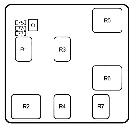
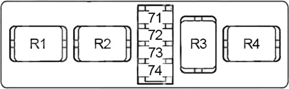
Relays
Assignment of the relays in the passenger compartment fuse box
Fuse Data
Full access is available to registered users — log in or register.
We use cookies to enhance your browsing experience, serve personalised ads or content, and analyse our traffic. By clicking "Accept All", you consent to our use of cookies. You can change or withdraw your consent at any time by clicking the consent preferences icon.
Customize Consent Preferences
We use cookies to help you navigate efficiently and perform certain functions. You will find detailed information about all cookies under each consent category below.
The cookies that are categorised as "Necessary" are stored on your browser as they are essential for enabling the basic functionalities of the site.
We also use third-party cookies that help us analyse how you use this website, store your preferences, and provide the content and marketing materials that are relevant to you. These cookies will only be stored in your browser with your prior consent.
You can choose to enable or disable some or all of these cookies but disabling some of them may affect your browsing experience.
Always Active
Necessary cookies are required to enable the basic features of this site, such as providing secure log-in or adjusting your consent preferences. They are not used for advertising or to track you across other sites. The consent cookie stores a random identifier that lets us keep a record of the choice you made.
Cookie
fazcookie-consent
Duration
6 months
Description
Stores the visitor's cookie consent choices and a random consent identifier used to keep a record of that choice.
Always Active
Functional cookies help perform certain functionalities like sharing the content of the website on social media platforms, collecting feedback, and other third-party features.
Cookie
__stripe_mid
Duration
1 year
Description
Stripe fraud prevention cookie for payment processing.
Cookie
__stripe_sid
Duration
30 minutes
Description
Stripe fraud prevention session cookie for payment processing.
Always Active
Analytical cookies are used to understand how visitors interact with the website. These cookies help provide information on metrics such as the number of visitors, bounce rate, traffic source, etc.
Cookie
_ga
Duration
2 years
Description
Google Analytics cookie used to distinguish users.
Cookie
_gid
Duration
24 hours
Description
Google Analytics cookie used to distinguish users.
Cookie
_gat
Duration
1 minute
Description
Google Analytics cookie used to throttle request rate.
Cookie
__utma
Duration
2 years
Description
Set by Google Analytics
Cookie
__utmb
Duration
30 minutes
Description
Set by Google Analytics
Cookie
__utmc
Duration
session
Description
Set by Google Analytics
Cookie
__utmz
Duration
6 months
Description
Set by Google Analytics
Cookie
__utmt
Duration
10 minutes
Description
Set by Google Analytics
Cookie
is_unique
Duration
Description
Set by StatCounter
Cookie
sc_is_visitor_unique
Duration
Description
Set by StatCounter
Always Active
Performance cookies are used to understand and analyse the key performance indexes of the website which helps in delivering a better user experience for the visitors.
No cookies to display.
Always Active
Cookies that have not yet been categorized.
No cookies to display.
Always Active
Marketing cookies are used to provide visitors with customised ads based on the pages you visited previously and to analyse the effectiveness of the ad campaigns.
Cookie
_gcl_au
Duration
90 days
Description
Google Ads conversion linker cookie.
Cookie
_gcl_aw
Duration
90 days
Description
Set by Google Ads
Cookie
IDE
Duration
1 year
Description
Set by Google Ads
Cookie
test_cookie
Duration
1 year
Description
Set by Google Ads
Opt-out Preferences
We use third-party cookies that help us analyse how you use this website, store your preferences, and provide the content and marketing materials that are relevant to you. However, you can opt out of these cookies by checking "Do Not Sell or Share My Personal Information" and clicking the "Save My Preferences" button. Once you opt out, you can opt in again at any time by unchecking "Do Not Sell or Share My Personal Information" and clicking the "Save My Preferences" button.
Do Not Sell or Share My Personal Information
Your opt-out settings for this website have been respected since we detected a Global Privacy Control signal from your browser and, therefore, you cannot change this setting.