The first-generation Toyota 86 —also known as the Toyota GT86 —was produced from 2012 to 2021 under model codes ZN6 and ZC6 . Developed in collaboration with Subaru (where it’s known as the BRZ), the 86 is a lightweight rear-wheel-drive sports car praised for its balanced handling, naturally aspirated boxer engine, and pure driving experience.
In this article, you will find fuse box diagrams for the Toyota 86, covering model years 2012, 2013, 2014, 2015, 2016, 2017, 2018, 2019, 2020 and 2021. These diagrams will help you understand the layout of the vehicle’s electrical fuses and relays—essential for diagnostics and basic maintenance.
What’s Included:
Fuse Box Diagrams – Clear illustrations showing the layout of fuses and relays for all covered model years.Fuse Panel Locations – Guidance on where to find the fuse boxes within the vehicle.Fuse Assignments – A complete list detailing what each fuse and relay controls to aid in troubleshooting.
Whether you’re replacing a blown fuse or diagnosing an electrical issue, this guide will support your maintenance work on the Toyota 86 / GT86 (2012–2021) efficiently and accurately.
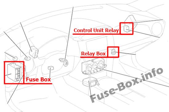
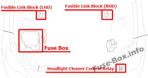
Left-hand drive vehicles
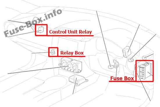
Right-hand drive vehicles
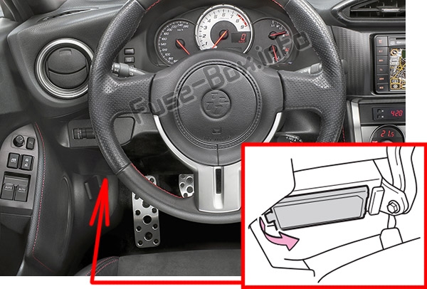
The fuse box is located under the instrument panel (on the driver’s side), under the lid.
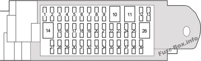
Assignment of the fuses in the Passenger Compartment
Fuse Data
Full access is available to registered users — log in or register.
Log in or register
№ Name Amp Circuit 1 P/POINT NO.1 15 Power outlet 2 RADIO 7.5 Audio system 3 SEAT HTR RH 10 Right-hand seat heater 4 SEAT HTR LH 10 Left-hand seat heater 5 ECU IG2 10 Engine control unit 6 GAUGE 7.5 Gauge and meters 7 AT UNIT 15 Transmission 8 – – – 9 – – – 10 – – – 11 – – – 12 – – – 13 AMP 15 Audio system 14 – – – 15 AM1 7.5 Starting system 16 – – – 17 – – – 18 – – – 19 – – – 20 ECU IG1 10 ABS, electric power steering 21 BK/UP LP 7.5 Back-up lights 22 FR FOG RH 10 Right-hand front fog light 23 FR FOG LH 10 Left-hand front fog light 24 HEATER 10 Air conditioning system 25 HEATER-S 7.5 Air conditioning system 26 – – – 27 OBD 7.5 On-board diagnosis system 28 – – – 29 – – – 30 STOP 7.5 Stop lights 31 – – – 32 – – – 33 – – – 34 DRL 10 Daytime running light system 35 – – – 36 TAIL 10 Tail lights 37 PANEL 10 Illumination 38 P/POINT NO.2 15 Power outlet 39 ECU ACC 10 Main body ECU, outside rear view mirrors
This content requires JavaScript and a valid membership to view.
Fuse Data
Full access is available to registered users — log in or register.
Log in or register
№ Name Amp Circuit 1 – – – Relay R1 Blower Motor
This content requires JavaScript and a valid membership to view.
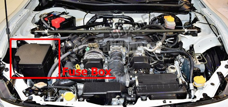
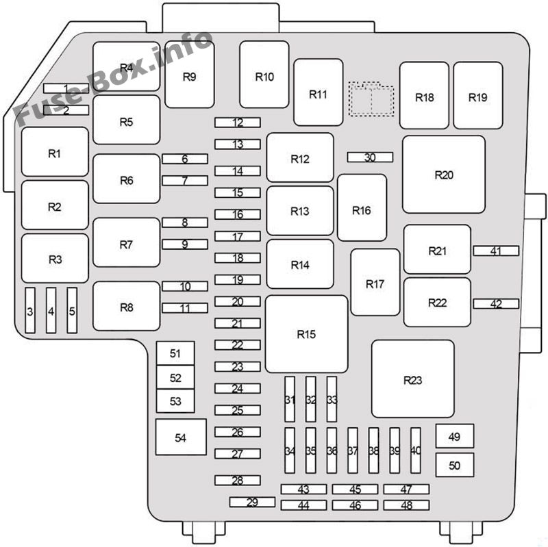
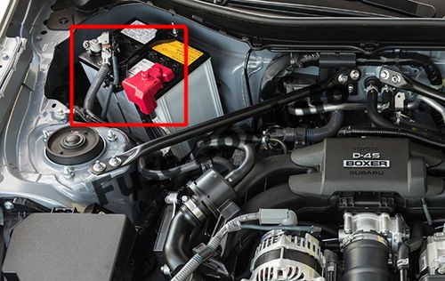
Assignment of the fuses and relay in the Engine Compartment
Fuse Data
Full access is available to registered users — log in or register.
Log in or register
№ Name Amp Circuit 1 A/B MAIN 15 SRS airbag system 2 – – – 3 IG2 7.5 Engine control unit 4 DOME 20 Interior light 5 ECU-B 7.5 Wireless remote control, main body ECU 6 HORN NO.2 7.5 Horn 7 HORN NO.1 7.5 Horn 8 H-LP LH LO 15 Left-hand headlight (low beam) 9 H-LP RH LO 15 Right-hand headlight (low beam) 10 H-LP LH HI 10 Left-hand headlight (high beam) 11 H-LP RH HI 10 Right-hand headlight (high beam) 12 ST 7.5 Starting system 13 ALT-S 7.5 Charging system 14 STR LOCK 7.5 Steering lock system 15 D/L 20 Power door lock 16 ETCS 15 Engine control unit 17 AT+B 7.5 Transmission 18 AM2 NO.2 7.5 Smart entry & start system 19 – – – 20 EFI (CTRL) 15 Engine control unit 21 EFI (HTR) 15 Multiport fuel injection system/sequential multiport fuel injection system 22 EFI (IGN) 15 Starting system 23 EFI (+B) 7.5 Engine control unit 24 HAZ 15 Turn signal lights, emergency flashers 25 MPX-B 7.5 Automatic air conditioning system, gauge and meters 26 F/PMP 20 Multiport fuel injection system/sequential multiport fuel injection system 27 IG2 MAIN 30 SRS airbag system, engine control unit 28 DCC 30 “ECU-B”, “DOME” fuses 29 – – – 30 PUSH-AT 7.5 Engine control unit 31 – – – 32 WIPER 30 Windshield wipers 33 WASHER 10 Windshield washer 34 D FL DOOR 25 Power window 35 ABS NO.2 25 ABS 36 D-OP 25 – 37 CDS 25 Electric cooling fan 38 D FR DOOR 25 Power window 39 RR FOG 10 Rear fog light 40 RR DEF 30 Rear window defogger 41 MIR HTR 7.5 Outside rear view mirror defoggers 42 RDI 25 Electric cooling fan 43 – – Spare fuse 44 – – Spare fuse 45 – – Spare fuse 46 – – Spare fuse 47 – – Spare fuse 48 – – Spare fuse 49 ABS NO.1 40 ABS 50 HEATER 50 Air conditioning system 51 INJ 30 Multiport fuel injection system/sequential multiport fuel injection system 52 H-LP WASHER 30 Headlight cleaners 53 AM2 NO.1 40 Starting system, engine control unit 54 EPS 80 Electric power steering Relay R1 (EFI MAIN1) R2 Electric cooling fan (FAN NO.3) R3 Heater R4 (EFI MAIN3) R5 (ETCS) R6 Horn R7 (H-LP) R8 Dimmer (DIM) R9 (EFI MAIN2) R10 Fuel pump (C/OPEN) R11 Inhibitor R12 with Front Marker Light: (DRL RH) R13 Starter (ST CUT) R14 (IGS) R15 Rear window defogger (RR DEF) R16 Starter (ST) R17 Ignition (IG2) R18 with Front Marker Light: (DRL LH) R19 Electric cooling fan (FAN NO.2) R20 (INJ) R21 Outside rear view mirror defoggers (MIR HTR) R22 Electric cooling fan (FAN NO.1) R23 Windshield wipers (WIPER)
This content requires JavaScript and a valid membership to view.
Fuse Data
Full access is available to registered users — log in or register.
Log in or register
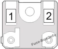
№ Name Amp Circuit 1 ALT 140 Charging system 2 MAIN 80 Horn relay, headlight relay, dimmer relay, “ALT-S”, “ETCS”, “F/PMP”, “MPX-B”, “HAZ”, “EFI (+B)”, “EFI (IGN)”, “EFI (HTR)”, “EFI (CTRL)”, “AT+B”, “IG2 MAIN”, “AM2 NO.2”, “EPS”, “INJ”, “AM2 NO.1”, “H-LP WASHER”, “STR LOCK”, “DCC”, “D/L” fuses
This content requires JavaScript and a valid membership to view.