The first-generation Toyota Aurion was produced from 2006 to 2012 under the model code XV40. Positioned as a premium mid-size sedan, it was developed primarily for markets such as Australia and New Zealand and offered refined styling, strong V6 performance, and a well-appointed interior.
In this article, you will find fuse box diagrams for the Toyota Aurion, covering model years 2006, 2007, 2008, 2009, 2010, 2011 and 2012. These diagrams are essential for understanding the fuse layout, making it easier to identify, inspect, and replace fuses and relays tied to key electrical systems.
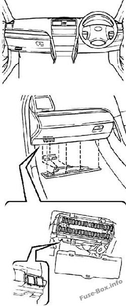
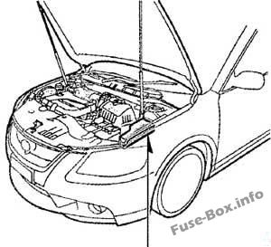
Fuse Panel Locations – Step-by-step information on where the fuse panels are located in the vehicle.
Fuse Assignments – A complete reference of what each fuse and relay controls, assisting in electrical troubleshooting and repairs.
Whether you’re tracking down a blown fuse or solving an electrical fault, this guide will help you maintain and repair your Toyota Aurion (2006–2012) with confidence.
Stop lights, high mounted stoplight, shift lock control system, multiport fuel injection system / sequential multiport fuel injection system, anti-lock brake system, vehicle stability control system, traction control system, brake assist system
8
TI&TE
30
Driving position memory system
9
–
–
–
10
AM1
7.5
Starting system, multiport fuel injection system / sequential multiport fuel injection system
11
A/C
7.5
Air conditioning system
12
PWR
25
Power windows
13
DOOR NO.2
25
Main body ECU
14
S/ROOF
30
Electric moon roof
15
TAIL
15
Tail lights, licence plate lights, parking lights, front fog lights, auto headlight levelling system
16
PANEL
7.5
Emergency flashers, air conditioning system, audio system, clock, glove box light, instrument panel lights, steering switches, navigation system, automatic transmission, rear electric sun shade
17
ECU IG NO.1
10
Main body ECU, electric moon roof, electric cooling fans, windshield wipers and washer, multi-information display, clock, Toyota parking assist-sensor, driving position memory system, auto antiglare inside rear view mirror, charging system, vehicle stability control system, smart entry and start system, rear view monitor system
18
ECU IG NO.2
7.5
Anti-lock brake system, vehicle stability control system, traction control system, brake assist system, shift lock control system, cruise control system, automatic transmission
19
A/C NO.2
10
Air conditioning system, rear window defogger
20
WASH
10
Windshield wipers and washers
21
–
–
–
22
GAUGE NO.1
10
Emergency flashers, back-up lights, charging system, navigation system, rear electric sun shade
23
WIP
25
Windshield wipers and washer
24
H-LP LVL
7.5
Auto headlight levelling system
25
TRAILER
20
Trailer wiring module
INJ
15
Multiport fuel injection system / sequential multiport fuel injection system, starting system
26
IGN
10
Multiport fuel injection system / sequential multiport fuel injection system, SRS airbag system, smart entry and start system, steering lock system, stop lights, electronic throttle control system
27
GAUGE NO.2
7.5
Gauges and meters, multi-information display, clock
28
ECU-ACC
7.5
Clock, main body ECU, shift lock control system, outside rear view mirrors, smart entry and start system, multi-information display
29
CIG
20
Cigarette lighter
30
PWR OUTLET
20
Power outlet
31
RADIO NO.2
7.5
Audio system, navigation system
32
MIR HTR
10
Outside rear view mirror defoggers
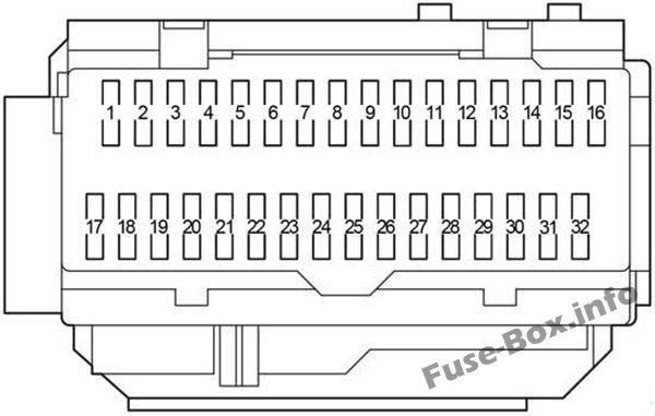
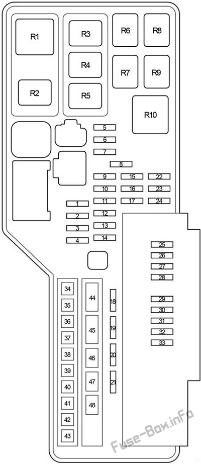
Assignment of the fuses in the Passenger Compartment
Fuse Data
Full access is available to registered users — log in or register.
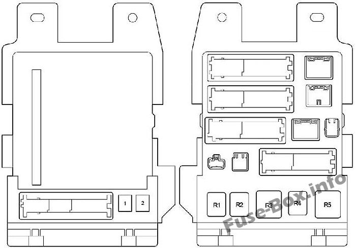
Multiport fuel injection system / sequential multiport fuel injection system, starting system, “GAUGE NO.2” and “IGN” fuses
14
STR LOCK
20
Steering lock system
15
DOME
10
Gauges and meters, vanity lights, boot light, ignition switch light, door courtesy lights, interior light, personal lights, clock, smart entry and start system, side turn signal lights
16
ECU-B NO.1
10
Main body ECU, vehicle stability control system, wireless remote control system, multiinformation display, driving position memory system, windshield wipers, rear view monitor system
17
RADIO NO.1
15
Audio system, navigation system
18
DOOR NO.
25
Main body ECU
19
–
–
–
20
AMP
25
Audio system, navigation system
21
EFI MAIN
30
Multiport fuel injection system / sequential multiport fuel injection system, automatic transmission, “EFI NO.2” and “EFI NO.3” fuses
22
–
–
–
23
EFI NO.3
10
Multiport fuel injection system / sequential multiport fuel injection system
24
EFI NO.2
15
Multiport fuel injection system / sequential multiport fuel injection system
25
S-HORN
7.5
Horn
26
A/F
20
Multiport fuel injection system / sequential multiport fuel injection system
27
MPX-B
10
Gauges and meters
28
EFI NO.1
10
Multiport fuel injection system / sequential multiport fuel injection system, smart entry and start system, automatic transmission
29
HORN
10
Horns
30
H-LP (RL)
15
Right-hand headlight (low beam), headlight levelling system
31
H-LP (LL)
15
Left-hand headlight (low beam)
32
H-LP(RH)
15
Right-hand headlight (high beam)
33
H-LP (LH)
15
Left-hand headlight (high beam)
34
HTR
50
Air conditioning system
35
ABS NO.1
50
Anti-lock brake system, vehicle stability control system, traction control system, brake assist system
36
FAN MAIN
50
Electric cooling fans
37
ABS NO.2
30
Anti-lock brake system, vehicle stability control system, traction control system, brake assist system