The third-generation Toyota Avalon (model code XX30 ) was produced from 2004 to 2012 . As Toyota’s flagship sedan in North America during this period, it offered a spacious interior, smooth ride quality, and a strong focus on luxury and reliability.
In this article, you will find fuse box diagrams for the Toyota Avalon, covering model years 2004, 2005, 2006, 2007, 2008, 2009, 2010, 2011 and 2012. These diagrams provide essential information to help you identify and replace blown fuses and troubleshoot electrical issues.
What’s Included:
Fuse Box Diagrams – Visual layouts showing fuse and relay arrangements.Fuse Panel Locations – Guidance on where to locate the fuse boxes in the vehicle.Fuse Assignments – A breakdown of each fuse and relay’s function for easier diagnosis and repair.
Whether you’re replacing a fuse or resolving an electrical malfunction, this guide will assist you in maintaining your Toyota Avalon (2004–2012) effectively.
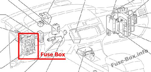
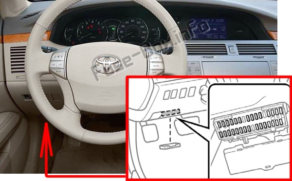
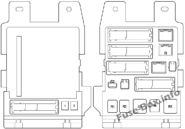
The fuse box is located under the instrument panel (on the driver’s side), under the cover.
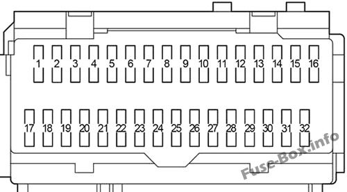
Assignment of the fuses in the Passenger Compartment
Fuse Data
Full access is available to registered users — log in or register.
Log in or register
№ Name Amp Circuit 1 RR DOOR 25 2005-2009: Power window (for rear right passenger) 1 RR DOOR 20 2010-2012: Power window (for rear right passenger) 2 RL DOOR 25 2005-2009: Power window (for rear left passenger) 2 RL DOOR 20 2010-2012: Power window (for rear left passenger) 3 FR DOOR 25 2005-2009: Power window (front passenger), driving position memory system 3 FR DOOR 20 2010-2012: Power window (front passenger), driving position memory system 4 FOG 15 Front fog lights 5 OBD 7.5 On-board diagnosis system 6 MPX-B 7.5 Multiplex communication system 7 – – – 8 P/W 25 2005-2009: Power widow, driving position memory system 8 FL DOOR 20 2010-2012: Power window, driving position memory system 9 FUEL OPN 7.5 Fuel filler door opener 10 AM1 7.5 Multiport fuel injection system/sequential multiport fuel injection system, starting system, ignition system 11 A/C 7.5 Air conditioning system 12 S-HTR 20 2008-2012: Air conditioning system 13 DOOR NO.2 25 Multiplex communication system 14 S/ROOF 30 Electric moon roof 15 TAIL 10 Parking lights, license plate lights, tail lights, front and rear side marker lights 16 PANEL 7.5 Seat heaters, navigation system, emergency flasher, electronically controlled automatic transmission system, glove box light, instrument panel lights, power outlets 17 ECU IG NO.1 7.5 2005-2006: Center display, shift lock control system, electric moon roof, multiplex communication system 17 ECU IG NO.1 10 2007-2012: Center display, shift lock control system, electric moon roof, multiplex communication system, tire pressure monitoring (warning) system 18 ECU IG NO.2 7.5 Anti-lock brake system, dynamic laser cruise control system, automatic headlight leveling system, vehicle stability control system, multiplex communication system 19 HTR 7.5 Air conditioning system, instrument panel lights, electric cooling fan 20 A/C COMP 7.5 Air conditioning system 21 S-HTR 20 2005-2007: Air conditioning system 22 GAUGE NO.1 10 Back-up lights, navigation system, emergency flashers 23 WIP 30 Windshield wipers 24 RR S/SHADE 10 Rear electric sunshade 25 – – Not used 26 IGN 10 Multiport fuel injection system/sequential multiport fuel injection system, engine immobilizer system, SRS airbag system, front passenger occupant classification system, smart key system, starter system 27 GAUGE NO.2 7.5 Gauges and meters, center display 28 ECU-ACC 7.5 Power rear view mirrors, center display, shift lock system, multiplex communication system 29 CIG 15 Cigarette lighter 30 PWR OUTLET 15 Power outlet 31 RADIO NO.2 7.5 Audio system 32 MIR HTR 10 Outside rear view mirror defoggers
This content requires JavaScript and a valid membership to view.
Fuse Data
Full access is available to registered users — log in or register.
Log in or register
№ Name Amp Circuit 1 P/SEAT 30 Power seats 2 POWER 30 Power windows Relay R1 Fog Lights R2 Tail Lights R3 Accessory Relay (ACC) R4 Power Relay (PWR) R5 Ignition (IG1)
This content requires JavaScript and a valid membership to view.
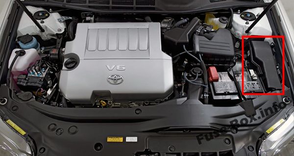
The fuse box is located in the engine compartment (left-side)
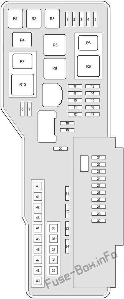
Assignment of the fuses and relay in the Engine Compartment
Fuse Data
Full access is available to registered users — log in or register.
Log in or register
№ Name Amp Circuit 1 EFI NO.2 10 Multiport fuel injection system/sequential multiport fuel injection system 2 STOP NO.2 7.5 Stop lights, high mounted stoplight, vehicle stability control system, anti-lock brake system 3 RADAR CC 7.5 2005-2010: Vehicle stability control system 4 HEAD RH LWR 15 Right-hand headlight (low beam) 5 HEAD LH LWR 15 Left-hand headlight (low beam) 6 STOP No.3 7.5 2008-2012: Electronic controlled transmission system, multiport fuel injection system/sequential multiport fuel injection system 7 INJ 15 Multiport fuel injection system/sequential multiport fuel injection system 8 – – – 9 STOP NO.1 15 Multiplex communication system 10 STR LOCK 25 2005-2010: Steering lock system 10 STR LOCK 15 2011-2012: Steering lock system 11 IMMOBI 7.5 2005-2007: Engine immobilizer system, smart key system 11 EFI No.3 7.5 2008-2012: Smart key system, electronic controlled transmission system 12 AMP 30 Audio system 13 – – – 14 – – Short Pin NO.1 15 RAD NO.1 15 Audio system, center display, navigation system 16 ECU-B 10 Center display, multiplex communication system 17 DOME 7.5 Gauges and meters, clock, front personal lights, door courtesy lights, garage door opener, rear personal lights, trunk light 18 TURN/HAZ 15 Turn signal lights 19 IG2 25 Multiport fuel injection system/sequential multiport fuel injection system 20 – – – 21 S-HORN 7.5 Horn 22 WASHER 20 Windshield washer 23 A/F 25 Air fuel ratio sensor 24 HEAD RH UPR 15 Right-had headlight (high beam) 25 HEAD LH UPR 15 Left-hand headlight (high beam) 26 – – – 27 – – – 28 HORN 10 Horn 29 – – Horns 30 EFI NO.1 25 Multiport fuel injection system/sequential multiport fuel injection system, fuel pump 31 ETCS 10 Multiport fuel injection system/sequential multiport fuel injection system 32 ALT-S 7.5 Charging system 33 DOOR NO.1 25 Multiplex communication system 34 AM2 7.5 Starter system 35 ALT 120 Charging system, “RR DEF”, “ABS/VSC NO2.” “HEATER”, “ABS/VSC NO.1”, “RDI FAN”, “WASHER” and “S-HORN” fuses 35 ALT 140 Charging system, “RR DEF”, “ABS/VSC NO2.” “HEATER”, “ABS/VSC NO.1”, “RDI FAN”, “WASHER” and “S-HORN” fuses 36 – – – 37 MAIN 40 Headlights 38 – – – 39 ST/AM2 30 Starter system 40 HEATER 50 Air conditioning system 41 ABS/VSC NO.1 50 Anti-lock brake system, vehicle stability control system 42 RDI FAN 50 Electric cooling fan 43 ABS/VSC NO.2 30 Anti-lock brake system, vehicle stability control system 44 RR DEF 50 Rear windshield defogger, outside rear view mirror defoggers 45 – – – 46 – – – 47 – – – 48 – – – 49 – – – Relay R1 ST Starter R2 MG CLT Air conditioner compressor clutch R3 IG2 Ignition R4 BRK Stop lights R5 RR DEF Rear windshield defogger R6 ST CUT Starter R7 VSC NO.1 Vehicle stability control R8 FAN NO.1 Electric cooling fan R9 HEAD Headlight R10 VSC NO.2 Vehicle stability control
This content requires JavaScript and a valid membership to view.
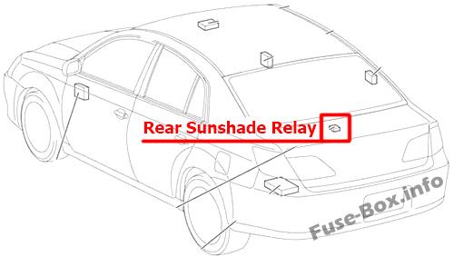
")
")
")
")