The sixth-generation Toyota Celica (Model Code: T200) was produced from 1993 to 1999. Known for its aerodynamic design and available all-wheel-drive GT-Four (ST205) variant, this generation of the Celica balanced sporty performance with Toyota’s reputation for reliability.
In this article, you will find fuse box diagrams for the Toyota Celica, covering model years 1993, 1994, 1995, 1996, 1997, 1998, and 1999. These diagrams help identify the fuse locations and assignments essential for maintaining your vehicle’s electrical systems.
What’s Included:
Fuse Box Diagrams – Detailed visuals showing the arrangement of fuses and relays.
Fuse Panel Locations – Instructions on where to locate fuse boxes within the vehicle.
Fuse Assignments – A comprehensive list of each fuse and relay’s purpose for easy troubleshooting.
Whether you’re addressing a faulty accessory or performing routine maintenance, this guide will assist you in keeping your Toyota Celica (1993–1999) running reliably and safely.
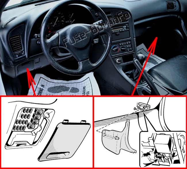
There are two fuse boxes in the passenger compartment. The first is behind the cover on the control panel, and the second is behind the cover on the passenger’s side kick panel.
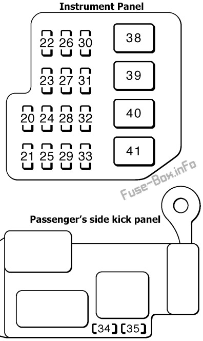
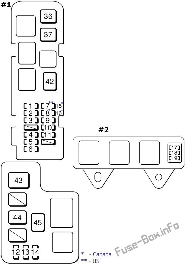
Fuse Box Diagram
Assignment of the fuses in the passenger compartment
Fuse Data
Full access is available to registered users — log in or register.
")