The second-generation Toyota Highlander Hybrid—also marketed as the Toyota Kluger in Australia—was introduced in 2007 and ran through 2010 in its pre-facelift form. Built on the XU40 platform, this hybrid SUV combined fuel efficiency with versatile performance, catering to families and eco-conscious drivers with advanced safety features and Toyota’s Hybrid Synergy Drive technology.
In this article, you will find fuse box diagrams for the Toyota Highlander Hybrid, covering model years 2007, 2008, 2009, and 2010. These diagrams help identify the location and purpose of each fuse and relay, which is critical for diagnostics, maintenance, and repairs.
What’s Included:
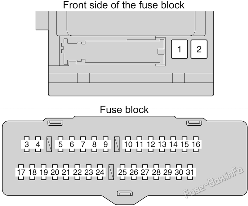
Fuse Box Diagrams – Clear illustrations detailing the layout of fuses and relays within the vehicle.
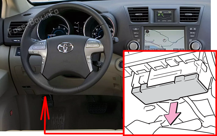
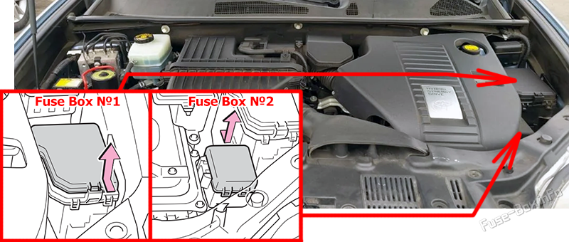
Fuse Panel Locations – Easy-to-follow instructions for locating fuse panels inside the cabin and under the hood.
Fuse Assignments – Comprehensive explanations of each fuse and relay’s function to support troubleshooting and electrical system management.
Whether you’re dealing with a blown fuse or installing new electronic components, this guide will help ensure the continued reliability and efficiency of your Toyota Highlander Hybrid (2007–2010).
Parking lights, tail lights, license plate lights, front fog lights, trailer lights
16
PANEL
7.5A
Glove box light, emergency flashers, audio system, outside rear view mirror defoggers, power door lock system, seat heaters, rear seat entertainment system, instrument panel light control dial, electronic controlled transmission switch, transmission, steering switches
17
ECU IG №1
10A
Multiplex communication system, electric moon roof, electronically controlled transmission system, power back door, seat heaters, tire pressure warning system, electronic power steering, transmission
Spare fuse (The spare fuses are located on the fusebox cover)
2
SPARE
15A
Spare fuse (The spare fuses are located on the fusebox cover)
3
SPARE
25A
Spare fuse (The spare fuses are located on the fusebox cover)
4
DEF RLY
10A
Rear window defogger
5
MIR HTR
20A
MIR HTR (15A)
6
P/OUT
20A
Power outlet
7
DOOR 1
25A
Multiplex communication system
8
IGCT №3
10A
Multiport fuel injection system / sequential multiport fuel injection system
9
EFI №3
10A
Multiport fuel injection system / sequential multiport fuel injection system
10
INJ №1
15A
Starting system
11
INJ №2
10A
Multiport fuel injection system / sequential multiport fuel injection system
12
HTR
50A
Air conditioning system
13
FAN №2
50A
Electric cooling fan
14
FAN №1
50A
Electric cooling fan
15
RR CLR
40A
Air conditioning system
16
RR DEF
30A
Rear window defogger
17
PBD
30A
Power back door
18
DC/DC
140A
MIR HTR, P/OUT, DOOR 1, HTR, RR DEF, FAN MAIN, PTC №1, RR CLR, PTC №2, PTC №3, PBD
19
EPS
80A
Electric power steering
20
ABS MTR1
50A
Brake system
21
ABS MTR2
50A
Brake system
22
CRT
10A
Rear seat entertainment system
23
RADIO1
15A
Audio system
24
ECU-B
10A
Steering sensor, gauges and meters, air conditioning system, main body ECU, wireless remote control, smart key system, power back door, on-board diagnosis system
25
DOME
10A
Vanity lights, personal lights, interior light, gauges and meters, door courtesy lights, power back door
26
AMP
15A
Audio system
27
TOWING
30A
Trailer lights
28
IG2
25A
INJ №1, INJ №2
29
STR LOCK
20A
Steering lock system
30
IGCT
30A
IGCT №2, IGCT №3, INV-W/P, EFI №3
31
HAZ
15A
Turn signal lights
32
ABS №3
15A
Electronically controlled brake system
33
ABS №2
10A
Electronically controlled brake system
34
ABS №1
10A
Capacitor
35
OIL PMP
10A
Transaxle fluid cooling system
36
BATT FAN
15A
Hybrid system
37
G/H
10A
Glass hatch, multiplex communication system
38
DC/DC-S
10A
Hybrid system
39
AM2
7.5A
Multiplex communication system
40
H-LP LH
15A
Left-hand headlight (high beam)
41
H-LP RH
15A
Right-hand headlight (high beam)
42
H-LP LL
15A
Left-hand headlight (low beam)
43
H-LP RL
15A
Right-hand headlight (low beam)
44
HORN
10A
Horn
45
EFI №1
10A
Multiport fuel injection system / sequential multiport fuel injection system, smart key system
46
ETCS
10A
Multiport fuel injection system / sequential multiport fuel injection system, electronic throttle control system
47
A/F
20A
Air fuel ratio sensor
48
S-HORN
7.5A
Horn
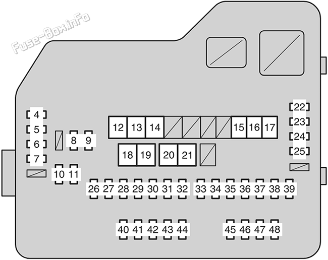
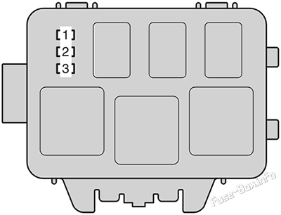
Fuse box diagram No.2
Assignment of the fuses in the Engine Compartment Fuse Box No.2
Fuse Data
Full access is available to registered users — log in or register.
")
")
")
")