The second-generation Toyota Land Cruiser Prado (Model Code: J90 ), produced from 1996 to 2002 , is a capable and dependable SUV that balanced off-road ruggedness with on-road comfort. Featuring body-on-frame construction, full-time four-wheel drive, and a range of diesel and gasoline engines, the J90 became a popular choice for adventure seekers and families alike.
In this article, you will find fuse box diagrams for the Toyota Land Cruiser Prado , covering model years 1996, 1997, 1998, 1999, 2000, 2001, and 2002 . These diagrams provide essential information for locating and identifying each fuse and relay in the vehicle.
What’s Included:
Fuse Box Diagrams – Easy-to-read diagrams that help you identify each fuse and relay by location and function.Fuse Panel Locations – Clear instructions to locate the interior and engine compartment fuse panels.Fuse Assignments – Complete descriptions of the purpose and amperage of each fuse and relay for troubleshooting and maintenance.
Whether you’re diagnosing an electrical issue or replacing a blown fuse, this guide is a practical tool to keep your Toyota Land Cruiser Prado (1996–2002) running smoothly and reliably in all driving conditions.
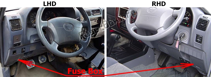
The fuse box is located on the driver’s side of the instrument panel, behind the cover.
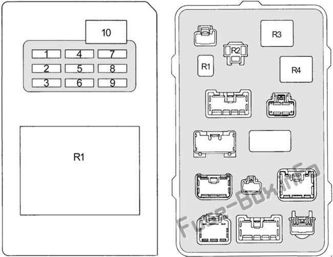
Assignment of the fuses and relays in the Passenger Compartment Fuse Box (Type 1)
Fuse Data
Full access is available to registered users — log in or register.
Log in or register
№ Name Description Amp 1 SEAT-HTR Seat heater 15 2 CIG Cigarette lighter, antenna, radio and player, airbag sensor assembly, remote control mirror switch 15 3 ECU-B Rear fog light, ABS ECU, wireless door lock ECU 15 4 DIFF 4WD control ECU 20 5 TURN Turn signal and hazard warning light 10 6 GAUGE Combination Meter, back-up light, alternator, rear heater relay, ABS warning light, cruise control indicator light, accessory meter, 4WD control ECU, “P” position switch, sub fuel tank gauge, power relay, defogger relay, rear window defogger switch, seat belt warning light, door courtesy light, neutral start switch 10 7 ECU-IG Antenna, ABS ECU, cruise control ECU, winch control and control switch, mirror heater switch, MIR HTR relay 15 8 WIPER Front wiper and washer, rear wiper and washer 20 9 IGN Airbag sensor assembly, EFI relay, charge warning light, transponder key computer, multiport fuel injection system/sequential multiport fuel injection system, pre-heating tamer, carburetor (3RZ-F) 7.5 10 POWER Power seat, integration relay (door lock), power windows, electric moon roof 30 Relays (front) R1 Integration relay Relays (back) R1 Horn R2 Turn signal flasher R3 Power relay R4 Defogger
This content requires JavaScript and a valid membership to view.
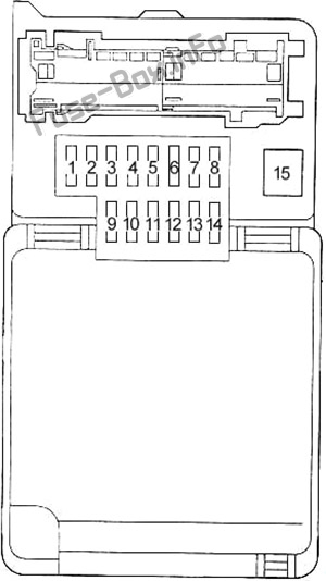
Assignment of the fuses in the Passenger Compartment Fuse Box (Type 2)
Fuse Data
Full access is available to registered users — log in or register.
Log in or register
№ Name Description Amp 1 ACC Cigarette lighter, radio and player, clock, air conditioning system, airbag sensor assembly, remote control mirror switch, seat belt 15 2 IGN Airbag sensor assembly, EFI relay, charge warning light, transponder key computer, multiport fuel injection system/sequential multiport fuel injection system, pre-heating tamer 10 3 CLOCK Clock 10 4 GAUGE Combination Meter, back-up light, alternator, rear heater relay, ABS warning light, cruise control indicator light, accessory meter, 4WD control ECU, “P” position switch, sub fuel tank gauge, power relay, defogger relay, rear window defogger switch, seat belt warning light, door courtesy light, neutral start switch 10 5 S-HTR Seat heater 15 6 HORN & HAZ Emergency flashers, horns 15 7 DIFF 4WD control ECU 20 8 ECU-B Rear fog light, cruise control, wireless door lock ECU 15 9 ST Starting system 5 10 WIPER Front wiper and washer, rear wiper and washer 20 11 STOP Stop lights, high mounted stop light, shift lock control system, anti−lock brake system 15 12 ECU-IG Anti−lock brake system, cruise control 15 13 DEF Rear window defogger 15 14 TAIL Tail light, license plate light, headlight beam level control, door courtesy light, meter illumination, instrument panel and switches illumination, daytime running light relay 10 15 POWER Power seat, integration relay (door lock), power windows, electric moon roof 30
This content requires JavaScript and a valid membership to view.
Fuse Data
Full access is available to registered users — log in or register.
Log in or register
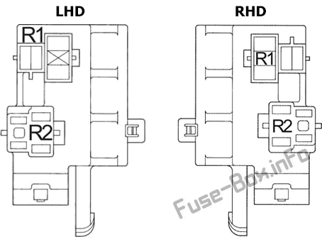
№ Relay R1 5VZ-FE, 3RZ-FE with sub fuel tank: Sub fuel pump forcing driving R2 –
This content requires JavaScript and a valid membership to view.
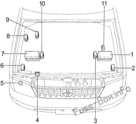
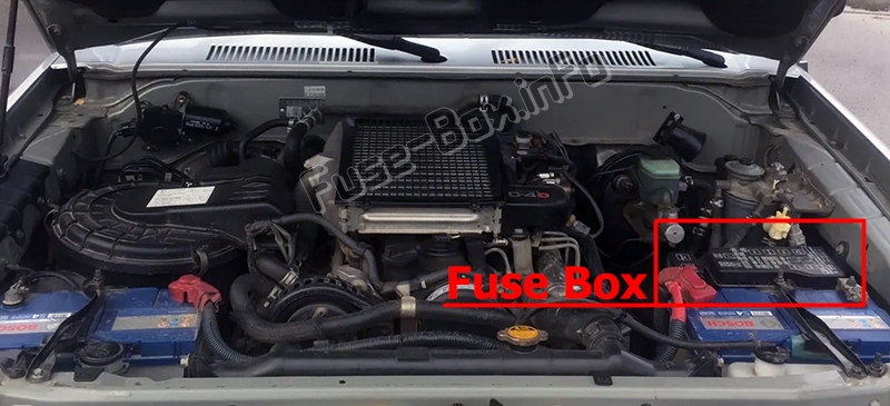
1) Fuse Box (Gasoline, LHD Diesel)
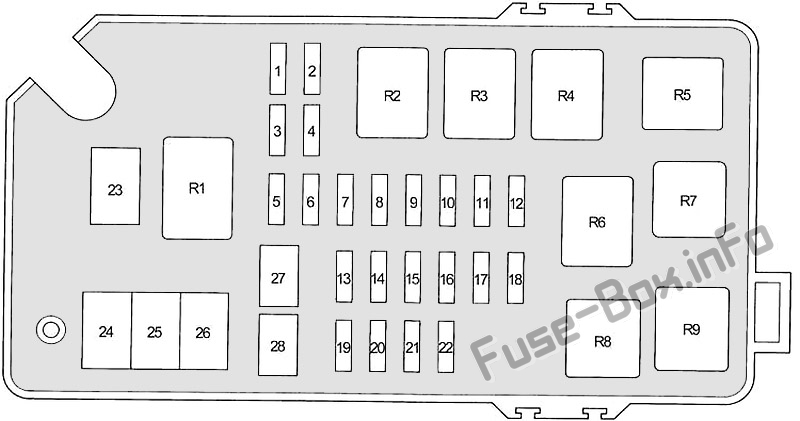
Assignment of the fuses and relays in the Engine Compartment
Fuse Data
Full access is available to registered users — log in or register.
Log in or register
№ Name Description Amp 1 PWR OUTLET (FR) Power outlets 20 2 PWR OUTLET (RR) Power outlets 20 3 FOG Fog lights 15 4 MIR HTR Outside rear view mirror heaters 15 5 TAIL Tail light, license plate light, headlight beam level control, door courtesy light, meter illumination, instrument panel and switches illumination, daytime running light relay 10 5 ETCS Anti−lock brake system 15 5 POWER HTR Air conditioning system 15 6 A.C. Air conditioning system 10 7 HEAD (LO RH) with DRL: Right-hand headlight (low beam) 10 8 HEAD (LO LH) with DRL: Left-hand headlight (low beam) 10 9 HEAD (RH) Right-hand headlight 10 9 HEAD (HI RH) with DRL: Right-hand headlight (high beam) 10 10 HEAD (LH) Left-hand headlight 10 10 HEAD (HI LH) with DRL: Left-hand headlight (high beam) 10 11 PTC HTR Viscous heater 10 12 ST Starter system 7.5 13 CDS FAN Electric cooling fan 20 14 DEFOG Rear window defogger 15 15 STOP Stop lights, high mounted stop light, shift lock control system, anti−lock brake system, vehicle stability control system 15 16 RR HTR Rear heater 10 16 OBD II On-board diagnosis system 7.5 17 ALT-S Charging system 7.5 18 RR A.C Rear air conditioning system 20 19 DOME Interior lights, personal lights, luggage room light, clock, audio system, odometer, antenna, open door warning light, integration relay 10 20 RADIO NO.2 Audio system 15 21 HAZ-HORN Emergency flashers, horns 15 22 EFI Multiport fuel injection system/sequential multiport fuel injection system 15 22 ECD 1KZ-TE: Multiport fuel injection system/sequential multiport fuel injection system 15 23 ABS Anti−lock brake system 60 23 ABS Anti−lock brake system, vehicle stability control system 100 24 HEATER Air conditioning system 60 25 GLOW Diesel: Engine glow system 80 26 ALT Tail light relay, “PWR OUTLET (FR)”, “PWR OUTLET (RR)”, “DEFOG”, “STOP”, “ALT-S”, “AM1”, “ABS” 100 26 ALT 1KZ-T, 3L: Tail light relay, “PWR OUTLET (FR)”, “PWR OUTLET (RR)”, “DEFOG”, “STOP”, “ALT-S”, “AM1” 80 27 AM1 Ignition switch, starter system, headlight cleaner relay, fuel heater, “ECU-B”, “GAUGE” “POWER” 50 28 AM2 Ignition switch, diode (glow plug), igniter, ignition coil and distributor (carburetor), “IGN” 30 Relays R1 Dimmer (LHD Europe) R2 5VZ-FE, 3RZ-FE: EFI R3 Outside rear view mirror heaters (MIR HTR) R4 Rear windshield defogger (DEFOG) R5 Power outlets (PWR OUTLET) R6 Tail lights R7 Starter (Gasoline (ST)) R8 Headlight (HEAD) R9 Heater
This content requires JavaScript and a valid membership to view.
Fuse Data
Full access is available to registered users — log in or register.
Log in or register
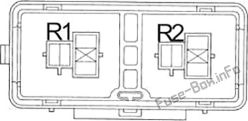
№ Relay R1 Air conditioner compressor clutch (MG CLT) R2 Electric cooling fan (CDS FAN)
This content requires JavaScript and a valid membership to view.
Fuse Data
Full access is available to registered users — log in or register.
Log in or register
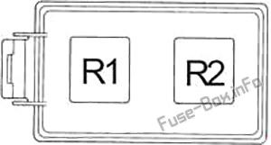
№ Relay R1 Starter (ST) R2 Glow system (SUB GLW)
This content requires JavaScript and a valid membership to view.
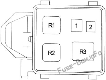
Fuse Data
Full access is available to registered users — log in or register.
Log in or register
№ Name Description Amp 1 ABS Anti−lock brake system 60 2 ABS Anti−lock brake system 40 Relays R1 Traction control system (TRC) R2 Anti−lock brake system (ABS MTR) R3 Anti−lock brake system (ABS SOL)
This content requires JavaScript and a valid membership to view.
")
")
")
")
")