The third-generation Toyota Sequoia (Model Code: XK80 ), produced from 2022 to the present , represents a bold evolution of Toyota’s full-size SUV. Built on the TNGA-F platform shared with the latest Tundra, the XK80 Sequoia offers a refined hybrid powertrain, advanced safety features, and modernized interior technology. Its combination of rugged capability and upscale comfort makes it a versatile choice for families and adventurers alike.
In this article, you will find fuse box diagrams for the Toyota Sequoia , covering model years 2022, 2023, 2024, 2025, and 2026 . These diagrams provide essential guidance for identifying fuses and relays, helping you maintain and troubleshoot the electrical systems in your vehicle.
What’s Included:
Fuse Box Diagrams – Clear and detailed illustrations to help locate and identify fuses and relays under the hood and in the cabin.Fuse Panel Locations – Guidance on where to find each fuse panel within the vehicle.Fuse Assignments – Explanations of the function of each fuse and relay, aiding accurate diagnostics and repairs.
Whether you’re replacing a faulty fuse, troubleshooting an electrical issue, or performing routine maintenance, this comprehensive guide ensures your Toyota Sequoia (2022–2026) remains dependable and road-ready.
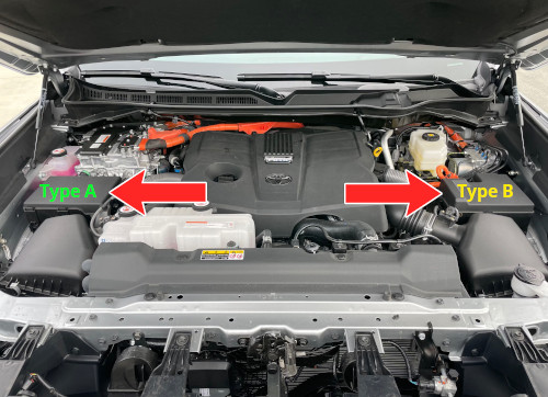
In the Toyota Sequoia’s engine compartment, there are two fuse boxes: fuse box type A and fuse box type B.
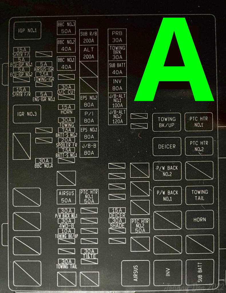
Assignment of the fuses in the Engine Compartments Type A Fuse box
Fuse Data
Full access is available to registered users — log in or register.
Log in or register
Amp No. Short-Code Explanation 15A F1 (S/HTR F/L) Front Seat Heater Left 5A F2 ECU-IGP NO.1 ECU Ignition Power No. 1 5A F3 ECU-IGP NO.2 ECU Ignition Power No. 2 15A F5 (S/HTR F/R) Front Seat Heater Right 5A F7 AIRSUS-IGR Air Suspension Ignition Relay 7.5A F8 TOWING-IGR Towing Ignition Relay 5A F10 ENG-IGR NO.1 Engine Ignition Relay No. 1 7.5A F12 INV W/PMP NO.2 Inverter Water Pump No. 2 7.5A F13 PM-IGCT Power Module – IGCT (Integrated Gate Commutated Thyristor) 7.5A F14 IGCT NO.4 IGCT Circuit No. 4 10A F15 PCU Power Control Unit (Hybrid System) 7.5A F16 IGCT NO.1 IGCT Circuit No. 1 7.5A F17 IGCT NO.2 IGCT Circuit No. 2 7.5A F18 IGCT NO.3 IGCT Circuit No. 3 40A F19 IGCT-MAIN Main IGCT Circuit 50A F20 (A/C RR) Rear Air Conditioning System 30A F21 (PBD) Power Back Door (Liftgate) 30A F23 D/C CUT DC Cutoff Circuit 20A F24 PFS NO.1 Power Fuse System No. 1 15A F25 (HORN) Horn Circuit 30A F26 (TOWING) Trailer Lighting Circuit 20A F29 PFS NO.2 Power Fuse System No. 2 15A F30 INV W/PMP NO.1 Inverter Water Pump No. 1 50A F32 AIRSUS Air Suspension System 50A F33 (PTC HTR NO.1) PTC Heater No. 1 30A F35 (4WD-B) 4WD Backup Circuit 10A F36 TOWING BK/UP Towing Backup Circuit 10A F37 G/H Grille Heater 30A F39 (TOWING TAIL) Trailer Tail Light Circuit 30A F44 (TI&TE) Power Tilt and Telescope Steering MUSB F49 (DC/DC) DC to DC Converter (400W) MUSB F52 (EPS NO.2) Electric Power Steering No. 2 MUSB F53 P/I Power Inverter MUSB F54 (EPS NO.1) Electric Power Steering No. 1 MUSB F55 (J/B-B) Junction Box Bus Line MUSB F56 PRB Power Relay Block MUSB F57 (TOWING BRK) Trailer Brake Circuit MUSB F58 SUB BATT Sub Battery Circuit MUSB F59 (INV) Power outlet (DC/AC inverter) Power Outlet – Inverter MUSB F60 J/B-ALT NO.1 Junction Box – Alternator No. 1 MUSB F61 J/B-ALT NO.2 Junction Box – Alternator No. 2 15A F66 (DEICER) Windshield Wiper Deicer 30A F67 SHADE Power Sunshade 10A F69 LED BEAM LED Headlight System 30A F70 (CDS FAN) A/C Condenser Cooling Fan 50A F72 (FAN NO.1) Main Radiator Cooling Fan 50A F73 (PTC HTR NO.2) PTC Heater No. 2 Relay R1 (IGP NO.1) Ignition Power Relay No. 1 Relay R2 IGR NO.3 Ignition Relay No. 3 Relay R3 IGCT IGCT System Relay Relay R6 TOWING BK/UP Trailer Backup Relay Relay R7 (DEICER) Defroster Relay Relay R10 INV W/PMP Inverter Water Pump Relay Relay R11 (CDS FAN) Condenser Fan Relay Relay R12 (PTC HTR NO.1) PTC Heater No. 1 Relay Relay R13 (PTC HTR NO.2) PTC Heater No. 2 Relay Relay R15 (TOWING TAIL) Trailer Tail Light Relay Relay R16 (HORN) Horn Relay Relay R18 AIRSUS Air Suspension Relay Relay R19 (INV) Power outlet (DC/AC inverter) Inverter Power Outlet Relay Relay R20 SUB BATT Sub Battery Relay
This content requires JavaScript and a valid membership to view.
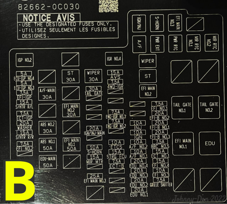
Assignment of the fuses in the Engine Compartments Type B Fuse box
Fuse Data
Full access is available to registered users — log in or register.
Log in or register
Amp No. Short-Code Explanation 7.5A F3 EFI NO.2 Electronic Fuel Injection Circuit No. 2 15A F4 S/HTR R/R Rear Seat Heater Right 20A F5 WASHER Windshield Washer Motor 7.5A F6 ECT-IGP Transmission – Ignition Power 15A F7 S/HTR R/L Rear Seat Heater Left 7.5A F8 EFI-IGP EFI – Ignition Power 5A F9 ECU-IGP NO.3 ECU – Ignition Power No. 3 5A F10 ECU-IGP NO.4 ECU – Ignition Power No. 4 50A F11 EDU-MAIN Main Power for Electronic Drive Unit (Hybrid) 50A F12 ABS NO.1 ABS Circuit No. 1 50A F13 ABS NO.2 ABS Circuit No. 2 30A F14 ABS MAIN NO.1 Main ABS Power No. 1 30A F15 A/F-MAIN Main Power for Air/Fuel Ratio Sensor 50A F17 OIL PMP Electric Oil Pump (Hybrid Transmission) 50A F18 EFI MAIN NO.1 Main EFI Circuit No. 1 50A F19 ABS MTR NO.1 ABS Motor Circuit No. 1 30A F20 EFI MAIN NO.2 Main EFI Circuit No. 2 30A F22 ST Starter Motor Circuit 25A F24 EFI MAIN NO.3 Main EFI Circuit No. 3 7.5A F25 ABS MAIN NO.2 Main ABS Circuit No. 2 15A F26 MIR MTR Mirror Adjustment Motor 10A F27 S-HORN Secondary Horn 20A F29 IGN/INJ-MAIN Main Ignition and Injector Power 30A F34 WIPER Windshield Wiper Motor 7.5A F38 ECT-B Transmission Secondary Control Circuit 15A F39 STRG ECU Steering ECU 10A F40 ETCS Electronic Throttle Control System 7.5A F42 ENG-IGR NO.2 Engine Ignition Relay No. 2 7.5A F43 ENG-IGR NO.3 Engine Ignition Relay No. 3 7.5A F46 4WD-IGR Four-Wheel Drive Ignition Relay 15A F47 AVS Adaptive Variable Suspension 20A F48 EDU NO.1 Electronic Drive Unit No. 1 20A F49 EDU NO.2 Electronic Drive Unit No. 2 20A F50 EDU NO.3 Electronic Drive Unit No. 3 20A F51 EDU NO.4 Electronic Drive Unit No. 4 10A F52 A/F NO.1 Air/Fuel Ratio Sensor No. 1 10A F53 A/F NO.2 Air/Fuel Ratio Sensor No. 2 10A F54 IGN Ignition Circuit 10A F55 INJ Fuel Injector Circuit 7.5A F58 GRILLE SHUTTER Active Grille Shutter System 10A F59 EFI NO.3 Electronic Fuel Injection Circuit No. 3 15A F60 EFI NO.4 Electronic Fuel Injection Circuit No. 4 15A F61 ECT NO.1 Transmission Control Circuit No. 1 7.5A F62 FAN NO.2 Cooling Fan No. 2 20A F63 EFI-B NO.3 Backup EFI Circuit No. 3 20A F64 EFI-B NO.1 Backup EFI Circuit No. 1 20A F65 EFI-B NO.2 Backup EFI Circuit No. 2 7.5A F66 EFI NO.1 Electronic Fuel Injection Circuit No. 1 Relay R1 IGP NO.2 Ignition Power Relay No. 2 Relay R2 IGR NO.4 Ignition Relay No. 4 Relay R3 EFI MAIN NO.2 EFI Main Relay No. 2 Relay R4 ST Starter Relay Relay R5 WIPER Wiper Motor Relay Relay R6 A/F Air/Fuel Sensor Relay Relay R7 PWR EXT External Power Relay Relay R8 PWR RTC Real-Time Clock Power Relay Relay R9 MIR RTC NO.1 Mirror RTC Power Relay No. 1 Relay R10 MIR RTC NO.2 Mirror RTC Power Relay No. 2 Relay R11 IGN/INJ Ignition/Injector Relay Relay R12 S-HORN Secondary Horn Relay Relay R13 EFI MAIN NO.3 EFI Main Relay No. 3 Relay R15 EFI MAIN NO.1 EFI Main Relay No. 1 Relay R17 OIL PMP Oil Pump Relay Relay R18 EDU Electronic Drive Unit Relay
This content requires JavaScript and a valid membership to view.
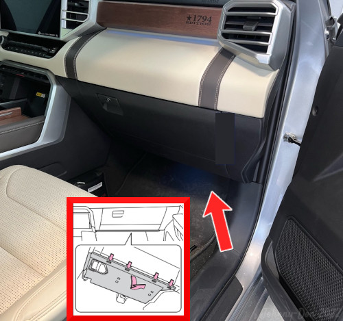
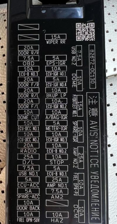
To access the passenger-side fuse box, remove the dash cover, disconnect the footwell light connector (if equipped), then press the claw to remove the lid.
Assignment of the fuses in the Passenger Compartment Fuse box
Fuse Data
Full access is available to registered users — log in or register.
Log in or register
Amp No. Short-Code Explanation 20A 3 (DOOR R/R) Rear right door 7.5A 4 (OBD) On-board diagnostics 10A 5 (ECU-B NO.3) Engine control unit 20A 6 (DOOR F/R) Front right door 20A 7 (DOOR R/L) Rear left door 20A 8 (DOOR F/L) Front left door lock 10A 9 (DOME CUT) Dome light and interior light 10A 10 (ECU-DCC NO.1) Engine control unit 10A 11 (ECU-DCC NO.2) Engine control unit 20A 12 (RADIO) Radio and audio system 25A 13 (D/L) Power door lock system 7.5A 14 (USB NO.1) USB charger 5A 15 (ECU-ACC) Engine control unit 10A 17 DOOR BACK Tailgate Door Control 10A 18 FUEL OPN-SUV Fuel Door Release (SUV) 15A 19 (WIPER RR) Rear wiper 5A 20 (EPS-IGR) Electric power steering 10A 21 (ECU-IGR NO.1) Engine control unit 5A 22 (ECU-IGR NO.4) Engine control unit 10A 23 (BKUP LP) Backup lights 10A 24 (ECU-IGR NO.2) Engine control unit 10A 25 (A/BAG-IGR) Airbag 5A 26 (METER-IGR) Instrument cluster 10A 27 (ECU-IGR NO.3) Engine control unit 10A 28 (ECU-B NO.2) Engine control unit 10A 29 (STOP) Stop lights 5A 30 (ECU-B NO.1) Engine control unit 25A 31 (AMP NO.1) Audio system 7.5A 32 (AM2) Starter system 10A 34 (HAZ) Hazard light 7.5A 35 (USB NO.2) USB charger 10A 36 (DOME) Dome light and interior light 15A 37 (P/OUTLET NO.1) Cigar lighter / power outlet 25A 39 (AMP NO.2) Audio system 10A 41 (DCM) Data communication module (telematics system)
This content requires JavaScript and a valid membership to view.
")
")