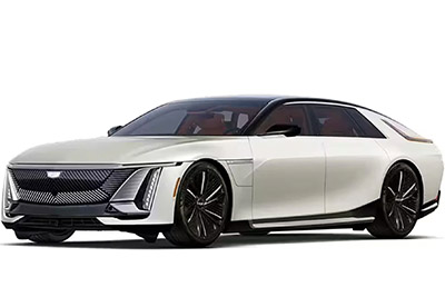
Discover Cadillac Celestiq fuse box diagrams for 2025–2026 models with fuse locations, panel layouts, electrical system details, and complete circuit assignments. This article covers the luxury battery electric liftback Cadillac Celestiq , available from 2025 , and includes fuse box diagrams for Cadillac Celestiq 2025 and 2026 , along with details about the location of the fuse panels inside the vehicle and a clear explanation of the assignment of each fuse (fuse layout).
NEED A REPLACEMENT?
Looking for the right fuse or relay?
Search common fuse types, fuse kits and relay options for your vehicle.
Find Fuses & Relays
→
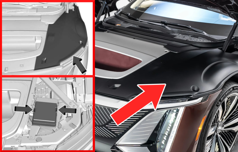
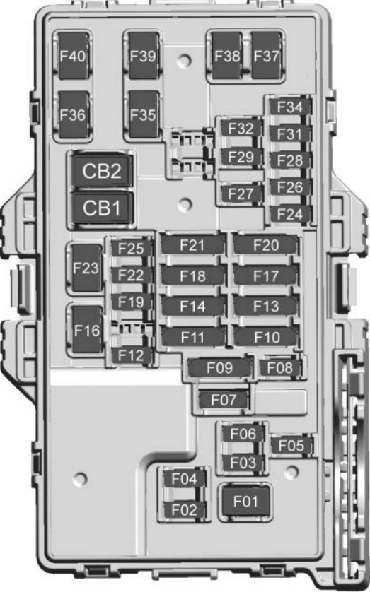
The fuse box is situated in the front compartment on the driver’s side, beneath the lid.
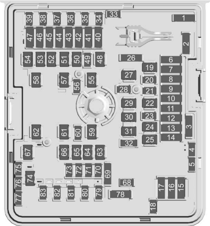
Assignment of the fuses in the front compartment
Fuse Data
Full access is available to registered users — log in or register.
Log in or register
No. Description F01 – F02 – F03 – F04 – F05 – F06 VICM – Vehicle Integration Control Module F07 PCEV – Primary Chiller Expansion Valve F08 SPARE F09 – F10 – F11 – F12 OBCM – On Board Charging Module F13 – F14 – F15 – F16 – F17 ARC FRT – Active Roll Control Front F18 GLVBX DR REL – Glove Box Door Release F19 – F20 – F21 CPDM – Charge Port Door Motor F22 – F23 PECP – Power Electronics Coolant Pump F24 – F25 – F26 – F27 – F28 CPDL – Charge Port Door Light F29 – F30 ESSCP – Energy Storage System Coolant Pump F31 – F32 – F33 – F34 ELM5 – Exterior Lighting 5 F35 ELM4 – Exterior Lighting 4 F36 2025: PFCM – Power Front Closure2026: –F37 – F38 ELM7 – Exterior Lighting 7 F39 ELM3 – Exterior Lighting 3 F40 HCAM DR – Heated Console Armrest Driver F41 HNSM DR – Heated Neck Scarf Module Driver F42 SPS PASS – Seat Position Switch Passenger F43 MCV – Main Coolant Valve F44 ACM – Aero Shutter Control Module F45 VKS – Virtual Key Sensor F46 CHIM – Charge Interface Module F47 PLCM – Power Line Communication Module F48 SAM RF2 – Side Access Module Right Front 2 F49 – F50 SAM RF1 – Side Access Module Right Front 1 F51 2025: –2026: PFCM – Power Front Closure ModuleF52 – F53 FRT WPR MTR – Front Wiper Motor F54 – F55 – F56 – F57 EBCM 2 – Electronic Brake Control Module 2 F58 – F59 – F60 Horn F61 – F62 2025: –2026: CRFM – Condenser Radiator Fan ModuleF63 – F64 SAM RR2 – Side Access Right Rear 2 F65 SAM RR1 – Side Access Right Rear 1 F66 2025: Cooling Fan ONE2026: –F67 WPR DICE – Wiper De-Ice F68 – F69 – F70 Relays Coil Ground F71 PRK EMBL LT – Park Emblem Light F72 – F73 NHT VSN WSH – Night Vision Camera Wash F74 – F75 – F76 – F77 – F78 – F79 – F80 – F81 – F82 Wash Pump Front F83 Camera Wash Pump
This content requires JavaScript and a valid membership to view.
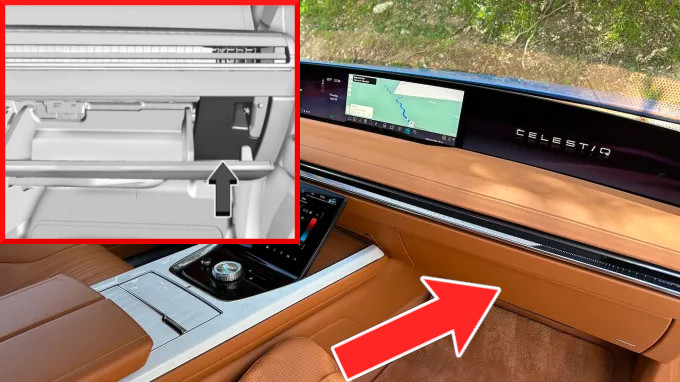
The instrument panel fuse block is located behind the glove box.
To access the fuse panel:
Open the glove box.
Starting at the bottom, carefully remove the access panel.
Once the retaining clips release, lift the panel away by disengaging the lower tabs from the instrument panel.
To reinstall the panel, insert the bottom tabs into their slots first, then rotate the panel into place until the retaining clips securely engage.
Assignment of the fuses in the passenger compartment
Fuse Data
Full access is available to registered users — log in or register.
Log in or register
No. Description F01 FRT BLWR – Front Blower F02 VCU 2 – Virtual Cockpit Unit 2 F03 SCL – Steering Column Lock F04 ELM 2 – Exterior Lighting Module 2 F05 BCM2 – Body Control Module 2 F06 VCU – Virtual Cockpit Unit F07 STR WHL CONTROL – Steering Wheel Controls F08 TCP – Telematics Control Platform F09 HVAC OUT LT MOD – Heating Ventilation Air Conditioning Outlet Module F10 UCDO – Universal Garage Door Opener F11 HTD DR ARMREST DRV 2 – Heated Door Armrest Driver 2 F12 SCL- Steering Column Lock F13 2025: –2026: SDM – Sensing & Diagnostic ModuleF14 IPE – Integrated Power Electronics F15 – F16 AC ELEC COMP – AC Electric Compressor F17 SRRS – Short Range Radar Sensors F18 SDM – Sensing & Diagnostic Module F19 TPIM – Traction Power Inverter Module F20 CCM – Central Gateway Module F21 FCC – Front Command Center F22 VICM – Vehicle Integration Control Module F23 2025: POWER OUTLET – Auxiliary USB ROW 1 / Auxiliary USB ROW 22026: USB ACC – USB Power Outlet RearF24 WCM 2 – Wireless Charger Module 2 F25 Spare F26 ELM – Exterior Lighting Module F27 2025-2026: AUX A/V – Auxiliary Audio/Video2025: JACK – Auxiliary Audio/VideoF28 ELM 6 – Exterior Lighting Module 6 F29 BCM1 – Body Control Module 1 F30 – F31 BCM3 – Body Control Module 3 F32 HSWM – Heated Steering Wheel Module F33 – F34 SCPM – Steering Column Position Module F35 SAM LF2 – Side Access Module Left Front 2 F36 2025: Blower Motor Control REAR2026: AMP 1 – Amplifier 1F37 HDLMP RT – Headlight Right F38 HDLMP LT – Headlight Left F39 BCM4 – Body Control Module 4 F40 SAM LF – Side Access Module Left Front
This content requires JavaScript and a valid membership to view.
Assignment of the circuit breakers in the passenger compartment
No. Description CB1 Spare CB2 Spare
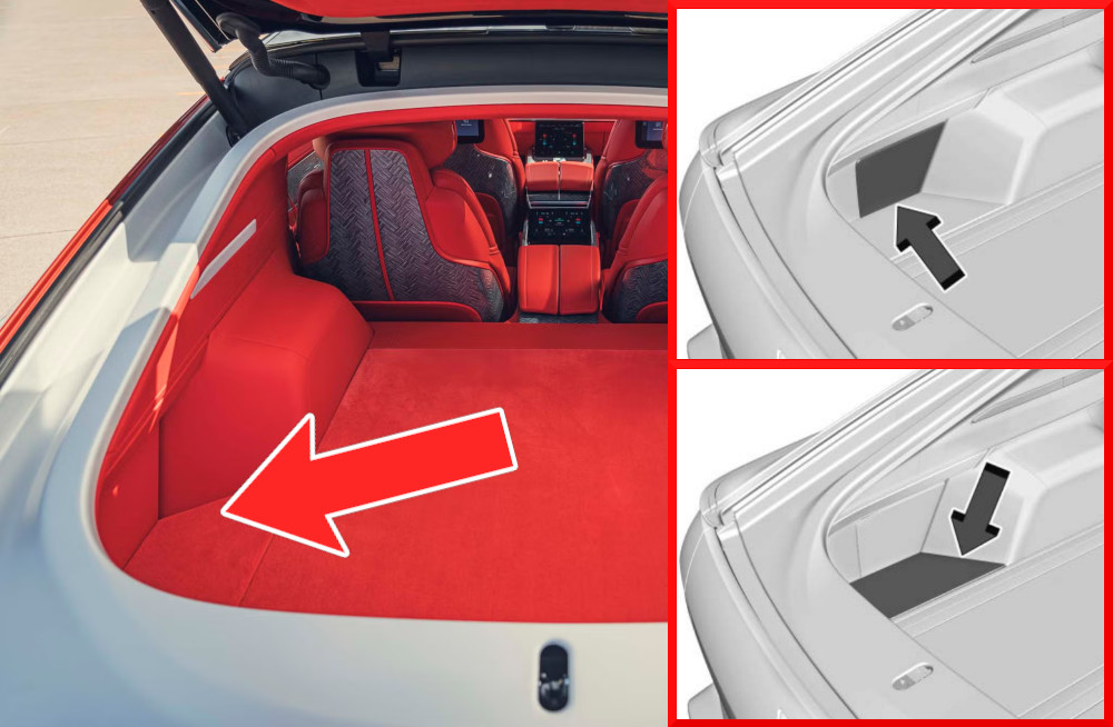
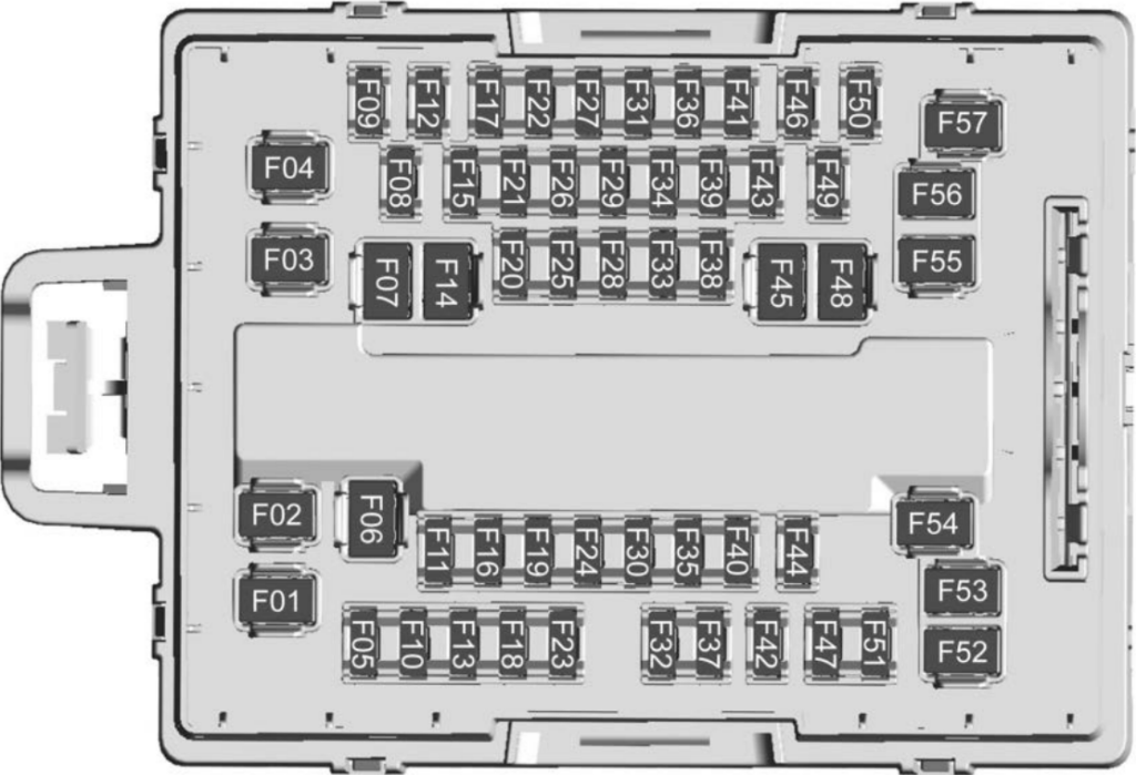
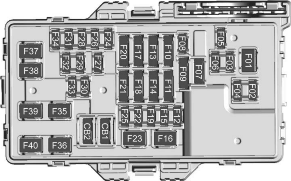
The rear compartment’s top and bottom fuse blocks are located behind a cover on the driver side of the rear compartment.
Assignment of the fuses in the rear compartment (Top)
Fuse Data
Full access is available to registered users — log in or register.
Log in or register
No. Description F01 MSM DR – Memory Seat Module Driver F02 MSM PASS – Memory Seat Module Passenger F03 MSM LR – Memory Seat Module LEFT REAR F04 VLM – Vehicle Leveling Module F05 ICCM – Integrated Chassis Control Module F06 2025: AMPLIFIER – Audio ONE_BAT 1F07 WNDW MTR RF – Window Motor Right Front F08 HVAC DISP R – HVAC Display Rear F09 TLMP RHT – Taillight Right F10 HTD DR ARMREST PASS R – Heated Door Armrest Passenger Rear F11 SPARE F12 SAM LR2 – Side Access Module Left Rear 2 F13 TLMP LFT – Taillight Left F14 HSM LR – Heated Seat Module Left Rear F15 TPIM1 – Traction Power Inverter Module 1 F16 SPARE F17 NVM – Night Vision Module F18 TPIM2 – Traction Power Inverter Module 2 F19 SPARE F20 SADOD – Side Access Door Object Detection Sensors F21 RFR – Radio Function Receiver F22 VKS – Virtual Key Sensors F23 SADS – Semi Active Dampening Suspension F24 2025: Traction Power Inverter BAT 3F25 AFL_AHL – Automatic Forward Lighting and Headlight Leveling F26 VLM – Vehicle Leveling Module F27 PAM – Park Assist Module F28 AMP 3 – Audio Amplifier 3 F29 RSI DISP RR – Rear Seat Infotainment (Right Rear) F30 SPARE F31 AAS – Auxiliary Alarm Sensor F32 MSM LR – Memory Seat Module Left Rear F33 2025: Sensing & Diagnostic / Automatic Occupant Sensing CO_DRIVERF34 VKBM – Virtual Key Backup Module F35 APM 48V – Auxiliary Power Module 48 Volts F36 ARS – Active Rear Spoiler F37 HCAM RR – Heated Console Armrest Module Right Rear F38 SPARE F39 MSM RF – Memory Seat Module Right Front F40 SPARE F41 RSI DISP LR – Rear Seat Infotainment Display Left Rear F42 ARC REAR – Active Roll Control Rear F43 WCM 4 – Wireless Charger Module 4 F44 SPARE F45 PWR WDW LF – Power Window Left Front F46 ACP3 – ADAS Compute Platform 3 F47 ROOF RGB – Roof Ambient Color Module F48 HSM LR – Heated Seat Module Left Rear F49 HCAM LR – Heated Console Armrest Module Left Rear F50 HDAM LR – Heated Door Armrest Module Left Rear F51 OBCM2 – Onboard Charging Module 2 F52 MSM RR – Memory Seat Module Right Rear F53 HSM RR – Heated Seat Module Right Rear F54 AMP 1 – Audio Amplifier 1 F55 HSM RR – Heated Seat Module Right Rear F56 SAM LR – SideAccessModule Left Rear F57 SPARE
This content requires JavaScript and a valid membership to view.
Assignment of the fuses in the rear compartment (Bottom)
Fuse Data
Full access is available to registered users — log in or register.
Log in or register
No. Description F01 HSM LF – Heated Seat Module Left Front F02 SPARE F03 MBM RF – Memory Bolster Module Right Front F04 BATT TNDR APO – Battery Tender Auxiliary Power Outlet F05 AMP2 2 – Audio Amplifier 2_2 F06 DSP LF – Door Switch Panel Left Front F07 – F08 – F09 MBM RR – Memory Bolster Module Right Rear F10 – F11 HTD/COOL SCM RR – Heated/ Cooled Seat Cushion Module Right Rear F12 SPARE F13 HTD/COOL SBM LF – Heated/ Cooled Seat Back Module Left Front F14 2025: –2026: ESTOP / SPAREF15 SPARE F16 2025: –2026: Blower RearF17 HTD/COOL SBM RF – Heated/ Cooled Seat Back Module Right Front F18 HDRST RF – Headrest Right Front F19 2025: –2026: COOL BOX – Cooler BoxF20 – F21 RFSI – Front Right Seat Infotainment F22 SPARE F23 SPARE F24 – F25 SPARE F26 HTD NCK SCRF RR – Heated Neck Scarf Right Rear F27 DSP RF – Door Switch Panel Right Front F28 HTD NCK SCRF LR – Heated Neck Scarf Left Rear F29 HTD/COOL SBM LR – Heated/ Cooled Seat Back Module Left Rear F30 – F31 AMP 2_1 – Audio Amplifier 2_1 F32 – F33 – F34 VLTS – Variable Light Transmission Sunshade F35 HSM LF – Heated Seat Module Left Front F36 PTM – Power Tailgate Module F37 SPARE F38 SPARE F39 HSM RF – Heated Seat Module Right Front F40 HSM RF2 – Heated Seat Module Right Front 2
This content requires JavaScript and a valid membership to view.
Assignment of the circuit breakers in the rear compartment (Bottom)