The second-generation Volvo C70 was produced from 2006 to 2013 . This model combined the elegance of a coupe with the practicality of a convertible, thanks to its innovative retractable hardtop. With refined styling, advanced safety technology, and solid performance, the C70 became a popular choice for those seeking both open-air driving and year-round usability.
In this article, you will find fuse box diagrams for the Volvo C70, covering model years 2006, 2007, 2008, 2009, 2010, 2011, 2012 and 2013. These diagrams are essential for understanding the fuse layout, helping owners and technicians locate, inspect, and replace fuses and relays as needed.
What’s Included:
Fuse Box Diagrams – Clear visuals showing the arrangement of fuses and relays.Fuse Panel Locations – Instructions on where to find the fuse panels inside the C70.Fuse Assignments – A detailed list of what each fuse and relay controls for easier diagnostics.
Whether you’re troubleshooting an electrical issue or replacing a blown fuse, this guide will help ensure your Volvo C70 (2006–2013) remains dependable and road-ready.
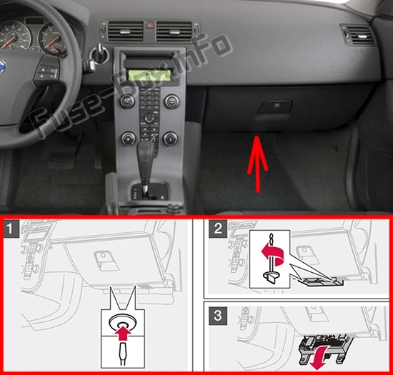
The fuse box is located under the glove compartment.
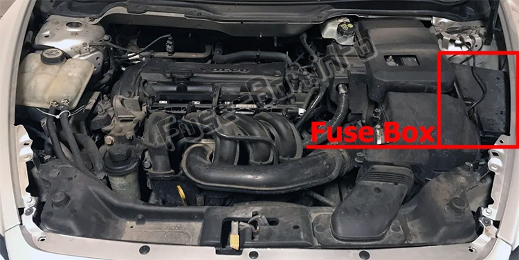
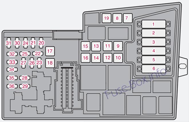
Assignment of fuses in the engine compartment
Fuse Data
Full access is available to registered users — log in or register.
Log in or register
№ Description Amp 1 Coolant fan (radiator) 50 A 2 Power steering 80 A 3 Feed to passenger compartment fuse box 60 A 4 Feed to passenger compartment fuse box 60 A 5 Climate unit element or not in use (depending on year) 80 A / Not in use 6 Not in use — 7 ABS pump 30 A 8 ABS valves 20 A 9 Engine functions 30 A 10 Climate system blower 40 A 11 Headlight washers, climate blower, hardtop system, storage lock 20 A 12 Feed to heated rear window 30 A 13 Starter motor relay 30 A 14 Trailer connector (accessory) 40 A 15 Retractable hard top system 30 A 16 Feed to audio system 40 A 17 Windshield wipers 30 A 18 Feed to passenger compartment fuse box 40 A 19 Not in use — 20 Horn 10 A or 15 A (depending on year) 21 Not in use — 22 Subwoofer (if equipped) 20 A or 25 A 23 Engine/Transmission Control Module (ECM/TCM) 10 A 24 Not in use — 25 Not in use — 26 Ignition switch 10 A or 15 A 27 A/C compressor 10 A 28 Not in use — 29 Front fog lights (option) 10 A or 15 A 30 Not in use — 31 Not in use — 32 Fuel injectors 10 A 33 Heated oxygen sensor; vacuum pump 20 A 34 Ignition coils; climate unit pressure sensor 10 A 35 Various engine sensors (valves, relays, filters, etc.) 10 A or 15 A 36 Engine control module (ECM), throttle sensor 10 A
This content requires JavaScript and a valid membership to view.
Fuses 1–18 are relays/circuit breakers and should only be removed or replaced by an authorized Volvo service technician.
Fuses 19–36 may be changed at any time when necessary.
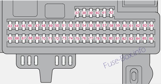
Assignment of fuses in the passenger compartment
Fuse Data
Full access is available to registered users — log in or register.
Log in or register
№ Description Amp 37 Not in use – 38 Not in use – 39 Not in use – 40 Not in use – 41 Not in use – 42 Not in use – 43 Audio system, Volvo Navigation system (option) 15 A 44 Supplemental Restrain System (SRS), engine control module 10 A 45 12-volt socket in passenger compartment 15 A 46 Lighting – glove compartment, instrument panel and footwells 5 A 47 Interior lighting 5 A 48 Windshield washers 15 A 49 Supplemental Restrain System (SRS), Occupant Weight Sensor (OWS) 10 A 50 Not in use – 51 Fuel filter relay 10 A 52 Transmission control module (TCM), ABS 5 A 53 Power steering 10 A 54 Park assist (option), Bi-Xenon® headlights (option) 10 A 55 Not in use – 56 Volvo Navigation System remote control (option), alarm siren control module 10 A 57 On-board diagnostic socket, brake light switch 15 A 58 Right high beam, auxiliary lights relay 5 A 59 Left high beam 5 A 60 Heated driver’s seat (option) 15 A 61 Heated passenger’s seat (option) 15 A 62 Not in use – 63 Power window – rear passenger’s side 20 A 64 Lock indicator lights door panels, Volvo Navigation system (option) 5 A 65 Audio system 5 A 66 Audio system control module (ICM), climate system 10 A 67 Not in use – 68 Cruise control 5 A 69 Climate system, rain sensor (option), BLIS button (option) 5 A 70 Not in use – 71 Not in use – 72 Not in use – 73 Front ceiling lighting 5 A 74 Fuel pump relay 15 A 75 Not in use – 76 Not in use – 77 12-volt socket in trunk, auxiliary equipment control module (AEM) 15 A 78 Not in use – 79 Back-up lights 5 A 80 Not in use – 81 Power window – rear driver’s side 20 A 82 Power window – front passenger’s side door 25 A 83 Power window & door lock – front driver’s side door 25 A 84 Power passenger’s seat (option) 25 A 85 Power driver’s seat (option) 25 A 86 Interior lighting relay, trunk lighting, power seats 5 A
This content requires JavaScript and a valid membership to view.