The third-generation Volvo V70, also known in its crossover form as the Volvo XC70, debuted in 2007 and continued production through 2010 before receiving a facelift. This pre-facelift model introduced improved safety features, increased cargo capacity, and enhanced comfort—making it a practical and refined choice for families and long-distance travelers.
In this article, you will find fuse box diagrams for the Volvo V70 / XC70, covering model years 2007, 2008, 2009 and 2010. These diagrams are helpful for understanding the electrical system layout, allowing you to inspect, replace, or troubleshoot fuses and relays as needed.
What’s Included:
Fuse Box Diagrams – Accurate illustrations showing the arrangement of fuses and relays for each specific model year.
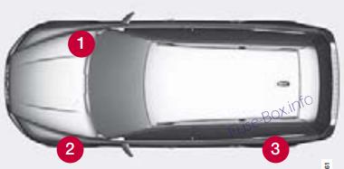
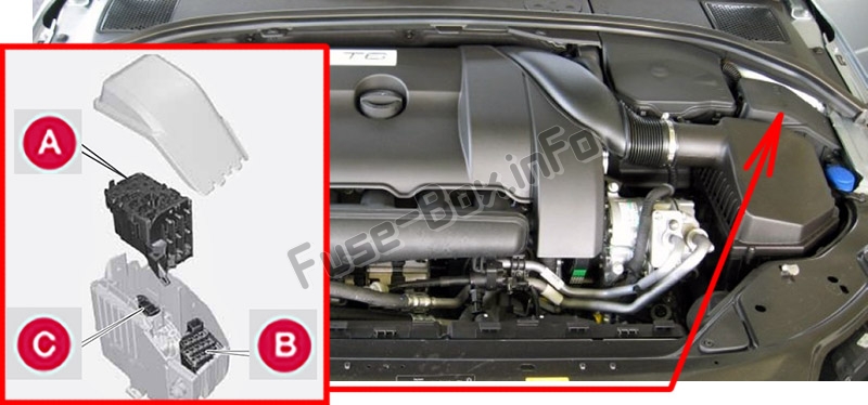
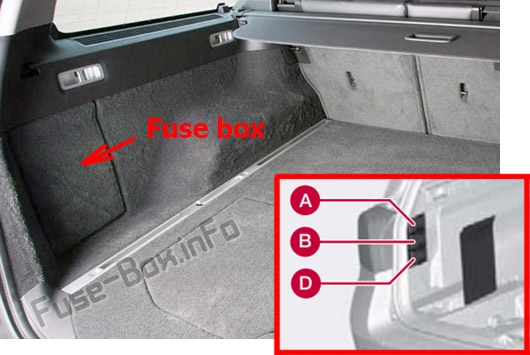
Fuse Panel Locations – Clear instructions on where to find fuse panels inside the vehicle (e.g., engine compartment, passenger footwell, cargo area).
Fuse Assignments – A complete breakdown of the function each fuse and relay supports—such as lights, climate control, power windows, and more.
Whether you’re fixing an electrical issue or performing regular maintenance, this guide provides all the information needed to manage your Volvo V70 / XC70 (2007–2010) with confidence.
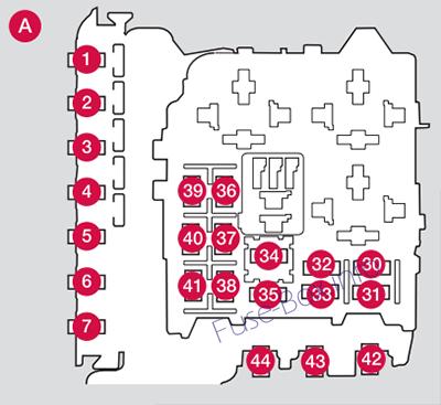
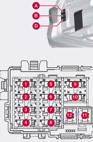
Fuses 16 —33 and 35 —41 are of the “MiniFuse” type. Fuses 8 —15 and 34 are of the “JCASE” type and must only be replaced by an authorised Volvo workshop. Fuses 1 —7 and 42 —44 are of the “Midi Fuse” type and must only be replaced by an authorised Volvo workshop.
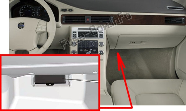
Under the glovebox
Assignment of fuses under the glovebox (2007, 2008)
Fuse Data
Full access is available to registered users — log in or register.
Fuses 16 —33 and 35 —41 are of the “MiniFuse” type. Fuses 8 —15 and 34 are of the “JCASE” type and must only be replaced by an authorised Volvo workshop. Fuses 1 —7 and 42 —44 are of the “Midi Fuse” type and must only be replaced by an authorised Volvo workshop.
Under the glovebox
Assignment of fuses under the glovebox (2009)
Fuse Data
Full access is available to registered users — log in or register.
Active Bending Lights. Headlight leveling (option)
10
17
Central electrical module
20
18
Radar. ACC control module (option)
5
19
Speed related power steering
5
20
Engine Control Module (ECM), transmission, SRS
10
21
Heated washer nozzles
10
22
Vacuum pump I5T
20
23
Lighting panel
5
24
Headlight washers
15
25
12-volt socket, front and rear seat; Rear Seat Entertainment (RSE) (option)
15
26
Moonroof (option), ceiling console/ ECC (option)
10
27
Engine compartment box
5
28
Auxiliary lights (option)
20
29
Horn
15
30
Engine Control Module (ECM)
10
31
Control module, automatic transmission
15
32
Compressor A/C
15
33
Coils
5
34
Starter motor relay
30
35
Ignition coils
20
36
Engine Control Module (ECM), throttle
10
37
Injection system
15
38
Engine valves
10
39
EVAP/heated oxygen sensor/ Injection
15
40
Crank case ventilation heater
10
41
Fuel leakage detection
5
42
–
43
–
44
Cooling fan
80
Fuses 16 – 33 and 35 – 41 may be changed at any time when necessary. Fuses 1 – 15, 34 and 42 – 44 are relays/ circuit breakers and should only be removed or replaced by a trained and qualified Volvo service technician.
Under the glovebox
Assignment of fuses under the glovebox (2010)
Fuse Data
Full access is available to registered users — log in or register.
")