The first-generation Volvo XC60, produced from 2008 to 2012, established itself as a premium compact SUV known for its elegant design, safety innovations, and Scandinavian engineering. Before its mid-cycle facelift in 2013, this model featured a clean aesthetic and a wide range of drivetrain options, appealing to both families and urban drivers.
In this article, you will find fuse box diagrams for the Volvo XC60, covering model years 2008, 2009, 2010, 2011 and 2012. These diagrams help identify fuses and relays responsible for various electrical systems, supporting quick and efficient troubleshooting.
What’s Included:
Fuse Box Diagrams – Detailed visuals of fuse and relay layouts for each applicable year.
Fuse Panel Locations – Exact positions of fuse boxes inside the vehicle (e.g., under the hood, behind the glove box, or in the trunk).
Fuse Assignments – A comprehensive list describing what each fuse and relay controls.
Whether you’re repairing a non-functioning accessory or investigating a warning light, this guide will assist in maintaining your Volvo XC60 (2008–2012) with accuracy and confidence.
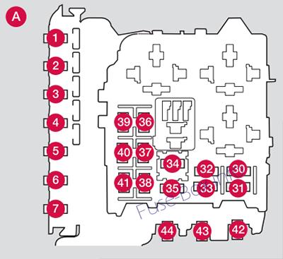
Active Dual Xenon Lights, Headlight leveling (option)
10
17
Central electrical module
20
18
Radar. ACC control module (option)
5
19
Speed-dependent power steering
5
20
Engine Control Module (ECM), transmission, SRS
10
21
Heated washer nozzles
10
22
Vacuum pump I5T
20
23
Lighting panel
5
24
Headlight washers
15
25
12-volt socket, front and rear seat
15
26
Moonroof (option), ceiling console/ ECC (option)
10
27
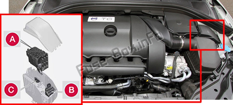
Engine compartment box
5
28
Auxiliary lights (option)
20
29
Horn
15
30
Engine Control Module (ECM)
10
31
Control module, automatic transmission
15
32
Compressor A/C
15
33
Coils
5
34
Starter motor relay
30
35
Ignition coils
20
36
Engine Control Module (ECM), throttle
10
37
Injection system
15
38
Engine valves
10
39
EVAP/heated oxygen sensor/ Injection
15
40
Crank case ventilation heater
20
41
Fuel leakage detection
5
42
43
44
Cooling fan
80
Fuses 16 – 33 and 35 – 41 may be changed at any time when necessary. Fuses 1 – 15, 34 and 42 – 44 are relays/ circuit breakers and should only be removed or replaced by a trained and qualified Volvo service technician.
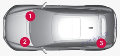
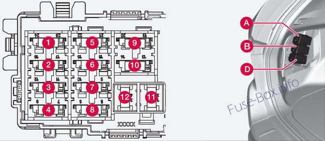
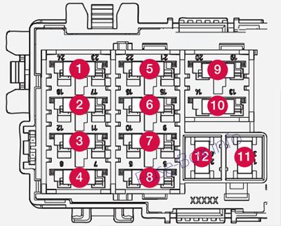
Under the glove compartment
Assignment of fuses under the glove compartment (2008, 2009, 2010)
Fuse Data
Full access is available to registered users — log in or register.
Active Dual Xenon Lights, Headlight leveling (option)
10
17
Central electrical module
20
18
ABS 15 feed
5
19
Speed-dependent power steering
5
20
Engine Control Module (ECM), transmission, SRS
10
21
Heated washer nozzles
10
22
Vacuum pump I5T
5
23
Lighting panel
5
24
25
26
27
Engine compartment box
5
28
Auxiliary lights (option)
20
29
Horn
15
30
Engine Control Module (ECM)
10
31
Control module, automatic transmission
15
32
Compressor A/C
15
33
Relay coils
5
34
Starter motor relay
30
35
Ignition coils
20
36
Engine Control Module (ECM), throttle
10
37
Injection system
15
38
Engine valves
10
39
EVAP/heated oxygen sensor/ Injection
15
40
Crank case ventilation heater
20
41
Fuel leakage detection
5
42
43
Cooling fan
80
44
Electro-hydraulic power steering
100
Fuses 16 – 33 and 35 – 41 may be changed at any time when necessary. Fuses 1 – 15, 34 and 42 – 44 are relays/ circuit breakers and should only be removed or replaced by a trained and qualified Volvo service technician.
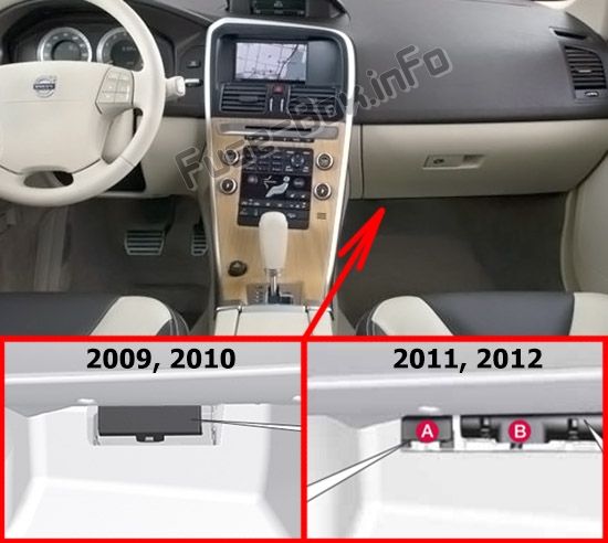
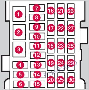
Under the glove compartment (Fusebox A)
Assignment of fuses under the glove compartment (Fusebox A – 2011)
Fuse Data
Full access is available to registered users — log in or register.
Active Dual Xenon Lights, Headlight leveling (option)
10
17
Central electrical module
20
18
ABS
5
19
Speed-dependent power steering
5
20
Engine Control Module (ECM), transmission, SRS
10
21
Heated washer nozzles
10
22
23
Lighting panel
5
24
25
26
27
Engine compartment box
5
28
Auxiliary lights (option)
20
29
Horn
15
30
Engine Control Module (ECM)
10
31
Control module, automatic transmission
15
32
Compressor A/C
15
33
Relay coils
5
34
Starter motor relay
30
35
Ignition coils
20
36
Engine Control Module
10
37
Injection system, mass air meter, engine control module
15
38
A/C compressor, engine valves, engine control module
10
39
EVAP valve, heated oxygen sensor
15
40
41
Fuel leakage detection
5
42
43
Cooling fan
80
44
Electro-hydraulic power steering
100
Fuses 16 – 33 and 35 – 41 may be changed at any time when necessary. Fuses 1 – 15, 34 and 42 – 44 are relays/ circuit breakers and should only be removed or replaced by a trained and qualified Volvo service technician.
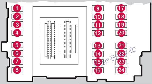
Under the glove compartment (Fusebox A)
Assignment of fuses under the glove compartment (Fusebox A – 2012)
Fuse Data
Full access is available to registered users — log in or register.