Mercedes-Benz CLS-Class Fuse Box Locations and Diagrams (2010-2017)
The second-generation Mercedes-Benz CLS-Class (C218 – four-door coupe; X218 – Shooting Brake) was produced from 2010 to 2017. Combining elegant styling, luxury, and sporty performance, this generation of the CLS-Class stood out with its distinctive design and a range of powerful engine options, including AMG variants.
In this article, you will find fuse box diagrams for the Mercedes-Benz CLS-Class, covering models CLS220, CLS250, CLS350, CLS400, CLS500, and CLS63 AMG for the years 2010, 2011, 2012, 2013, 2014, 2015, 2016, and 2017. These diagrams offer detailed insights into the fuse layout, helping you identify and understand the role of each fuse and relay in your vehicle.
What’s Included:
Fuse Box Diagrams – Visual layouts showing the location and configuration of each fuse, relay, and circuit breaker.
Fuse Panel Locations – Guidance on where to find the fuse panels inside your CLS-Class, including common locations like the passenger compartment, engine bay, and trunk.
Fuse Assignments – Clear explanations of what each fuse and relay is responsible for—covering systems like lighting, climate control, infotainment, engine management, and more.
Whether you’re dealing with a blown fuse, performing routine maintenance, or diagnosing an electrical issue, this guide serves as a valuable reference to keep your Mercedes-Benz CLS-Class (2010–2017) operating reliably.
Ensure your CLS-Class remains in peak condition with this complete fuse box, fuse panel, and relay assignment guide.
The cigar lighter (power outlet) fuses in the Mercedes-Benz CLS-Class are:
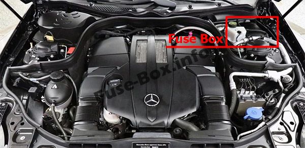
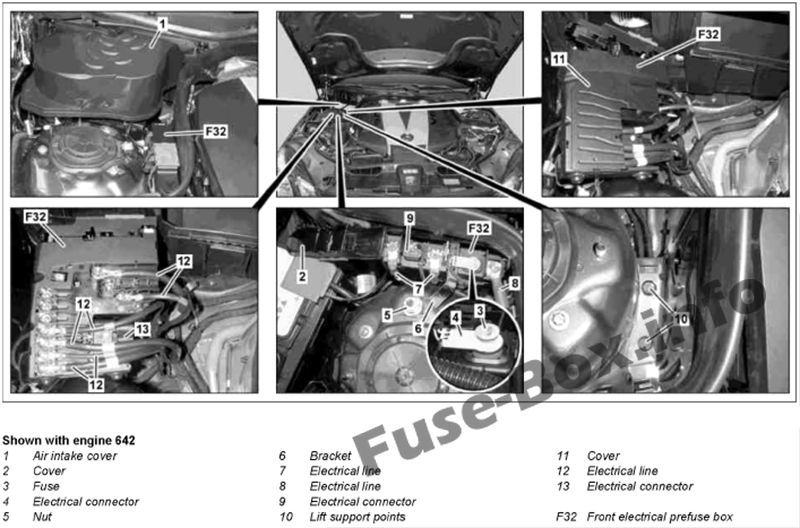
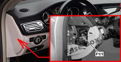
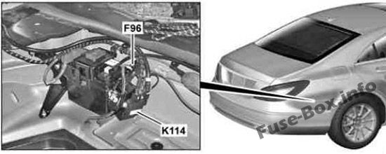
The fuse box is located in the engine compartment (left-side)
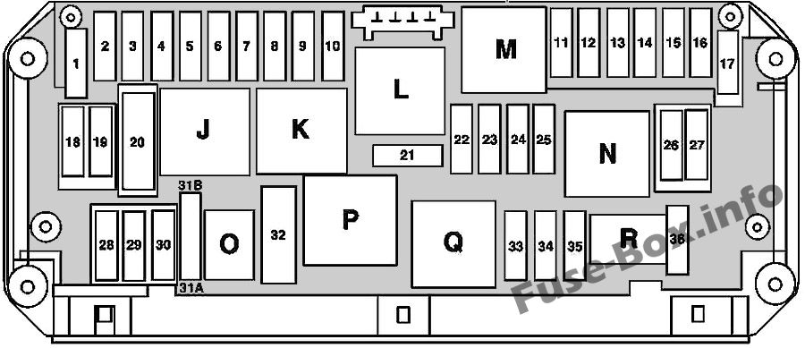
Fuse box diagram
Assignment of the fuses and relay in the engine compartment
№
Fused function
Amp
1
Electronic Stability Program control unit Premium Electronic Stability Program control unit Blower motor Blower regulator
25
2
Left front door control unit
30
3
Right front door control unit
30
4
Valid with engine 157: Fuel system control unit
20
5
Instrument cluster Rear SAM control unit with fuse and relay module Exterior lights switch
7.5
6
Valid for diesel engine: CDI control unit Valid for gasoline engine: ME-SFI control unit
10
7
Starter circuit 50 relay
20
8
Supplemental restraint system control unit
7.5
9
Center console socket
15
10
Wiper motor Switched via wiper park position heater relay: Wiper park position heater
30
11
Audio/COMAND display Audio/COMAND control panel
7.5
12
Automatic climate control control and operating unit Upper control panel control unit Automatic transmission transmission mode button Suspension button group
7.5
13
Steering column tube module control unit Multifunction camera Stereo multifunction camera
7.5
14
Electronic Stability Program control unit Premium Electronic Stability Program control unit
7.5
15
Supplemental restraint system control unit
7.5
16
Valid with engine 157: DIRECT SELECT INTERFACE
5
17
Electrical glass tilting/sliding roof: Overhead control panel control unit
30
18
Analog clock Backup relay
7.5
19
Electronic ignition lock control unit
20
20
Electronic Stability Program control unit Premium Electronic Stability Program control unit
40
21
Brake lights switch Glove compartment lamp switch Front passenger seat occupied recognition and ACSR Weight sensing system (WSS) control unit
7.5
22
Fan motor for internal combustion engine and air conditioning with integrated control Valid for diesel engine: CDI control unit Connector sleeve, circuit 87 Valid for gasoline engine: ME-SFI control unit Connector sleeve, circuit 87 M2e Valid with engine 276: Radiator shutters actuator
15
23
Valid for gasoline engine: Connector sleeve, circuit 87 M1i Valid for diesel engine: CDI control unit Connector sleeve, circuit 87
20
24
Valid for diesel engine: Connector sleeve, circuit 87 Valid for engine 157, 276, 278: Connector sleeve, circuit 87 M1e
15
25
Valid for diesel engine: Oxygen sensor upstream of catalytic converter Valid for gasoline engine: ME-SFI control unit
15
26
Radio Radio with auto pilot system COMAND controller unit
20
27
Valid for gasoline engine: ME-SFI control unit Valid for diesel engine: CDI control unit Electronic ignition lock control unit
7.5
28
Instrument cluster
7.5
29
Right front lamp unit
10
30
Left front lamp unit
10
31A
Switched through the horns relay: Left fanfare horn Right fanfare horn
15
31B
Switched through the horns relay: Left fanfare horn Right fanfare horn
15
32
Secondary air injection relay
–
33
Fully integrated transmission control controller unit
10
34
Fuel system control unit
7.5
35
Spare
–
36
Night View Assist control unit DISTRONIC electric controller unit
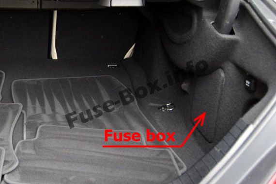
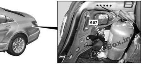
It is located on the right side of the luggage compartment, behind the cover.
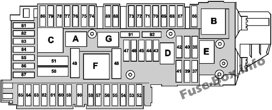
Fuse box diagram
Assignment of the fuses and relay in the trunk
№
Fused function
Amp
37
Driver seat NECK-PRO head restraint solenoid Front passenger seat NECK-PRO head restraint solenoid
7.5
38
Shooting Brake: Connected through liftgate windshield wiper relay: Tailgate wiper motor
15
39
Valid for left-hand drive vehicles:Left rear door control unit Valid for right-hand drive vehicles: Left front door control unit
30
40
Spare
–
41
Valid for left-hand drive vehicles: Right front door control unit Valid for right-hand drive vehicles: Right rear door control unit
30
42
Fuel system control unit
25
43
Valid up to 31.08.2014: Telematics services communications module (Live Traffic Information) Valid as of 01.09.2014:Tire pressure monitor control unit
7.5
44
Front passenger seat adjustment switch
30
45
Driver seat adjustment switch
30
46
Alarm siren (Interior monitoring) Interior protection and tow-away protection control unit (Interior monitoring) Coupe: M 1, AM, CL [ZV] and KEYLESS-GO antenna amplifier Shooting Brake: Rear window antenna amplifier 1 Valid with engine 157, 276, 278 and USA version: Coolant circulation pump relay
7.5
47
Spare
–
48
Spare
–
49
Coupe: Switched through the rear window heater relay: Rear window heater Shooting Brake: Switched through the rear window heater relay: Rear window antenna amplifier 1
40
50
Right front reversible emergency tensioning retractor
50
51
Left front reversible emergency tensioning retractor
50
52
Spare
–
53
Trailer recognition control unit
30
54
Trailer recognition control unit
15
55
Spare
–
56
Trailer socket
15
57
Trailer recognition control unit
25
58
Trailer recognition control unit
25
59
Left front bumper DISTRONIC (DTR) sensor Right front bumper DISTRONIC (DTR) sensor Left rear bumper radar sensor (Active Blind Spot Assist) Right rear bumper radar sensor (Active Blind Spot Assist) Left rear bumper intelligent radar sensor (Blind Spot Assist) Intelligent radar sensor for right rear bumper (Blind Spot Assist)
7.5
60
Multicontour seat pneumatic pump
7.5
60
Active multicontour seat pneumatic pump
30
61
Coupe: Trunk lid control (KDS) control unit Shooting Brake: Liftgate control unit
40
62
Driver seat control unit
25
63
Rear seat heater control unit
25
64
Front passenger seat control unit
25
65
Up to 31.05.2012: Steering wheel heater control unit As of 01.06.2012: Steering column tube module control unit
7.5
66
Rear blower motor
7.5
67
Sound system amplifier control unit
40
68
AIRmatic control unit
15
69
Rear bass speaker amplifier
25
70
Tire pressure monitor control unit Valid as of 01.09.2014 with engine 157, 276, 278 without USA version: Coolant circulation pump relay
5
71
Vehicle interior socket, front
15
72
Cargo area socket
15
73
Valid with engine 157: Transmission mode control unit Stationary heater: Stationary heater radio remote control receiver
5
74
KEYLESS-GO control unit Valid as of 01.09.2014: Left front lamp unit, Right front lamp unit
15
75
Stationary heater unit Valid as of 01.09.2014: Left front lamp unit, Right front lamp unit
20
76
Rear center console socket
15
77
Weight sensing system (WSS) control unit Navigation processor
7.5
78
Media interface control unit
7.5
79
Video and radar sensor system control unit Valid as of 01.09.2014 with Driving assistance package Plus: Radar sensors control unit, Chassis gateway control unit
5
80
Parking system control unit
5
81
Cellular telephone system antenna amplifier / compensator Mobile phone electrical connector
5
82
Left front seat ventilation blower regulator Right front seat ventilation blower regulator
7.5
83
Reversing camera Navigation processor Emergency call system control unit
7.5
84
Reversing camera control unit Reversing camera power supply module Reversing camera SDAR/high definition tuner control unit Digital Audio Broadcasting control unit
5
85
TV tuner (analog/digital) Digital TV tuner
7.5
86
Spare
–
87
Emergency call system control unit Valid up to 31.08.2014 with engine 157, 276, 278 without USA version: Coolant circulation pump relay Valid to 31.05.2016 with Live Traffic Information or eCall Europe emergency call system: Telematics services communications module Valid as of 01.06.2016: HERMES control unit Valid as from 01.06.2016 with Comfort telephony and Remote control for stationary heater: Antenna changeover switch for telephone and stationary heater
7.5
88
Intelligent servo module for DIRECT SELECT
15
89
Trailer recognition control unit Valid with engine 157: Fuel system control unit
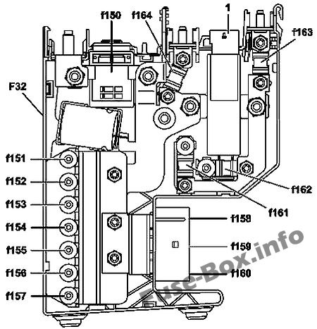
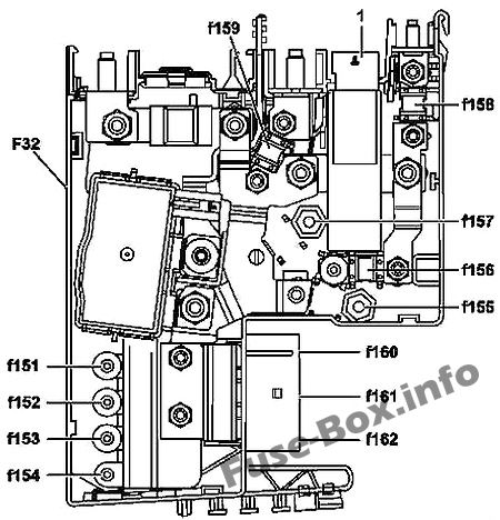
Fan motor for internal combustion engine and air conditioning with integrated control (M4/7)
100
155
Valid for diesel engine: PTC heater booster
150
156
Spare
–
157
Front SAM control unit with fuse and relay module
150
158
Valid for left-hand drive vehicles: Blower regulator Valid for right-hand drive vehicles without DISTRONIC PLUS or without engine 157: Electronic Stability Program control unit Valid with right-hand drive vehicles with DISTRONIC PLUS or with engine 157: Premium Electronic Stability Program control unit
50
159
Valid for right-hand drive vehicles without DISTRONIC PLUS or without engine 157: Electronic Stability Program control unit Valid with right-hand drive vehicles with DISTRONIC PLUS or with engine 157: Premium Electronic Stability Program control unit
50
160
AIRmatic relay
60
161
Spare
–
162
Front SAM control unit with fuse and relay module
100
163
Without ECO start/stop function: Rear SAM control unit with fuse and relay module
150
164
Without ECO start/stop: Rear SAM control unit with fuse and relay module
Protects the connection between the additional battery and the electronic ignition lock control unit and the front SAM control unit (for engine 276 as of 01.09.2014 or with engine 274)