Toyota Verso-S / Ractis / Space Verso (2010-2017)

The Toyota Verso-S, also known as the Toyota Ractis and Toyota Space Verso in various markets, was produced between 2010 and 2017 (Model Code: XP120). This subcompact MPV combined the practicality of a small hatchback with the space and flexibility of a mini-MPV, making it a popular choice for city driving, small families, and anyone needing a compact car with excellent interior space.

In this article, you will find fuse box diagrams for the Toyota Verso-S, covering model years 2010, 2011, 2012, 2013, 2014, 2015, 2016, and 2017. These diagrams are designed to help you quickly identify the location and function of each fuse and relay in the vehicle.

What’s Included:

  • Fuse Box Diagrams – Detailed illustrations showing the layout of fuses and relays in each fuse panel.
  • Fuse Panel Locations – Instructions on where to find the fuse boxes inside the cabin and engine compartment.
  • Fuse Assignments – A complete listing of the fuse and relay functions, assisting with troubleshooting and repairs.

Whether you’re tracking down an electrical fault, replacing a blown fuse, or working on routine maintenance, this guide offers a clear, concise reference. Keep your Toyota Verso-S / Ractis (2010–2017) running smoothly with the correct fuse and relay information at your fingertips.

Overview

Left-hand drive vehicles

The location of the fuses in the passenger compartment (LHD): Toyota Verso-S / Ractis (2010-2017)

Right-hand drive vehicles

The location of the fuses in the passenger compartment (RHD): Toyota Verso-S / Ractis (2010-2017)

Passenger Compartment

Fuse box location

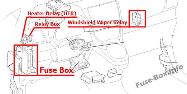
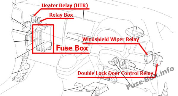
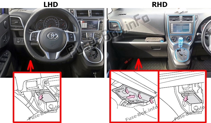
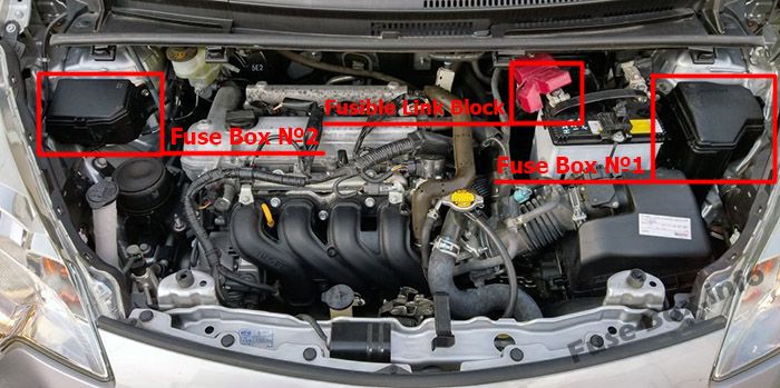
The fuse box is located under the instrument panel (on the left-side), under the cover.
Left-hand drive vehicles: Open the lid.
Right-hand drive vehicles: Remove the cover and open the lid.
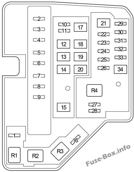
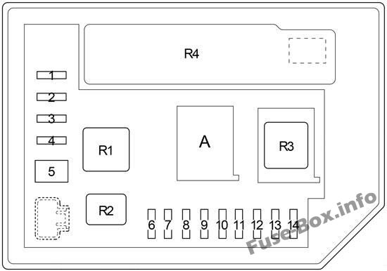
The location of the fuses in the passenger compartment: Toyota Verso-S / Racis (NCP120; 2010-2017)

Fuse box diagrams

Instrument panel fuse box diagram: Toyota Verso-S / Ractis (2010-2017)

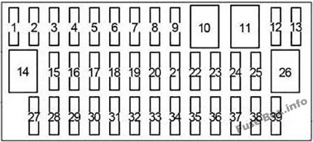
Assignment of the fuses in the Passenger Compartment

NameAmpCircuit
1
2
3
4S-HTR15Seat heaters
5
6
7
8SHADE25Panoramic roof shade
9
10
11
12D-D/L25Multiport fuel injection system/sequential multiport fuel injection system
13
14
15FOG FR15Front fog lights, gauge and meters
16AM17.5Starting system
17STOP7.5Multiport fuel injection system/sequential multiport fuel injection system, smart entry & start system, ABS, VSC, multi-mode manual transmission, stop lights, high mounted stoplight, shift lock control system
18FOG RR7.5Rear fog light, gauge and meters
19
20OBD7.5On-board diagnosis system
21D/L25Power door lock system
22ACC5Main body ECU, outside rear view mirrors, audio system, Stop & Start system, shift lock control system
23CIG15Power outlets
24DOOR20Power windows
25DOOR R/L20Power windows
26P/W30Power windows
27WIPER RR15Rear window wiper
28WIPER20Windshield wipers
29WASHER15Windshield washer
30
31
32GAUGE10Back-up light, shift lock control system, rear seat belt reminder lights, auto antiglare inside rear view mirror, multidrive, audio system, panoramic roof shade, multiport fuel injection system/sequential multiport fuel injection system, rain sensor
33A/C7.5Air conditioning system, power heater, rear window defogger, outside rear view mirror defoggers
34ECU-IG NO.25ABS, VSC, Stop & Start system
35ECU-IG NO.15Electric cooling fan, rear window defogger, electric power steering, main body ECU, windshield wipers, VSC
36DOOR P20Power windows
37DOOR R/R20Power windows
38PANEL5Gauge and meters, instrument panel lights, switch illumination
39TAIL NO.210Front position lights, tail lights, license plate lights, front fog lights, rear fog light, multiport fuel injection system/sequential multiport fuel injection system, gauge and meters

Login or Register to view this content

Relay Box

Relay
R1
R2Front fog light (FR FOG)

Login or Register to view this content

Engine Compartment

Fuse box location

The location of the fuses in the engine compartment: Toyota Verso-S / Ractis (2010-2017)

Fuse Box Diagram #1

Under-hood fuse box #1 diagram: Toyota Verso-S / Ractis (2010-2017)

Assignment of the fuses and relay in the Engine Compartment Fuse Box №1

NameAmpCircuit
1ID/UP7.5Multiport fuel injection system/sequential multiport fuel injection system
2EFI MAIN20Gasoline: Multiport fuel injection system/sequential multiport fuel injection system
2ECD MAIN30Diesel: Multiport fuel injection system/sequential multiport fuel injection system, “EFI NO.2” fuse
3EFI NO.37.5Multiport fuel injection system/sequential multiport fuel injection system
4HORN10Horn
5EFI NO.210Stop & Start system, multiport fuel injection system/sequential multiport fuel injection system
6IG210Smart entry & start system, multiport fuel injection system/sequential multiport fuel injection system, multi-mode manual transmission, SRS airbag system, steering lock system, stop lights, Stop & Start system
7IGN15Multiport fuel injection system/sequential multiport fuel injection system
8MET7.5Gauge and meters, Stop & Start system
9
10
11PWR HTR25Power heater, multiport fuel injection system/sequential multiport fuel injection system
12EPS50Electric power steering
13ABS NO.230ABS, VSC
14DEF30Rear window defogger
15PTC80PTC heater, outside rear view mirror defoggers
16
17HTR40Air conditioning system
18
19RDI FAN30Electric cooling fan
20ABS NO.150ABS, VSC
21BBC40Stop & Start system
22ST30Starting system
23
24D/L NO.225Power door lock
25D.C.C30“DOME”, “ECU-B NO.1” fuses
26STR LOCK20Steering lock system
27ECU-B NO.15Main body ECU, smart entry 8t. start system
28DOME15Interior lights, audio system, VSC
29ETCS10Multiport fuel injection system/sequential multiport fuel injection system
30HAZ10Turn signal lights
31AM27.5Multiport fuel injection system/sequential multiport fuel injection system, smart entry & start system, starting system, multi-mode manual transmission
32ECU-B NO.25Gauge and meters, power door lock, wireless remote control, Stop & Start system, smart entry & start system, multi-mode manual transmission, air conditioning system
33
34R/I50“EFI MAIN”, “ECD MAIN”, “EFI NO.2”, “EFI NO.3”, “IG2”, “IGN”, “MET”, “HORN” fuses
Relay
R1Electric cooling fan (FAN NO.2)
R2Electric cooling fan (FAN NO.1)
R3Rear window defogger (DEF)
R4Starting system (ST)
with Stop & Start System; 1NZ-FE: Starting system (ST2)

Login or Register to view this content

Fuse Box Diagram #2

A:

Under-hood fuse box #2 diagram: Toyota Verso-S / Ractis (2010-2017)

Type 1

Type 2

Engine Compartment Fuse Box №2

NameAmpCircuit
1
2EU-DRL15Headlight
3S-HORN10Multiport fuel injection system/sequential multiport fuel injection system
4H-LP MAIN7.5“H-LP RH LO”, “H-LP LH LO” fuses
5MMT50Multi-mode manual transmission
5ST40with Stop & Start System; 1NZ-FE: Starting system
6H-LP RH HI10Right-hand headlight (high beam)
7H-LP LH HI10Left-hand headlight (high beam), gauge and meters
8H-LP RH LO10Halogen: Right-hand headlight (low beam)
8H-LP RH LO15HID: Right-hand headlight (low beam)
9H-LP LH LO10Halogen: Left-hand headlight (low beam), manual headlight leveling dial
9H-LP LH LO15HID: Left-hand headlight (low beam), manual headlight leveling dial
10
11
12
13
14
Relay
R1Dimmer (DIM)
R2Daytime running lights / Theft deterrent (EU-DRL/S-HORN)
R3Headlight / Daytime running lights (H-LP/US-DRL)
R4Integration Relay
R51NR-FE, 1ND-TV: Daytime running lights (DRL)
with Stop & Start System 1NZ-FE: Starter ((ST) Before May 2014)
R61NR-FE, 1ND-TV: (O/P MTR)
R7Multi-mode manual transmission (MMT)

Login or Register to view this content

Fusible Link Block

It is located on the battery

Gasoline

Diesel

NameAmpCircuit
1GLOW DC/DC80Engine glow system
2MAIN80“BBC”, “S-HORN”, “ST”, “D/L NO.2”, “D.C.C.”, “STR LOCK”, “ETCS”, “HAZ”, “AM2”, “ECU-B NO.2”, “R/I”, “H-LP MAIN”, “H-LP RH HI”, “H-LP LH HI”, “H-LP RH LO”, “H-LP LH LO”, “MMT” fuses
3ALT120“PWR HTR”, “EPS”, “ABS NO.2”, “DEF”, “PTC”, “HTR”, “RDI FAN”, “ABS NO.1”, “TAIL NO.2”, “PANEL”, “DOOR R/R”, “DOOR P”, “ECU-IG NO.1”, “ECU-IG NO.2”, “A/C”, “GAUGE”, “WASHER”, “WIPER”, “WIPER RR”, “P/W”, “DOOR R/L”, “DOOR”, “CIG”, “ACC”, “D/L”, “OBD”, “FOG RR”, “STOP”, “AM1”, “FOG FR”, “D-D/L”, “SHADE”, “S-HTR” fuses

Login or Register to view this content

FAQ

Scroll to Top