The first-generation Toyota Highlander Hybrid —also known as the Toyota Kluger Hybrid in Australia—was produced from 2005 to 2007 under the model code MHU28 . As Toyota’s first mid-size SUV to feature hybrid technology, it combined the spaciousness and versatility of a crossover with the fuel efficiency of a hybrid powertrain, setting a new standard for eco-friendly family vehicles.
In this article, you will find fuse box diagrams for the Toyota Highlander Hybrid , covering model years 2005, 2006, and 2007 . These diagrams are essential for understanding the fuse layout, helping you locate, inspect, or replace fuses and relays related to key electrical systems.
What’s Included:
Fuse Box Diagrams – Detailed visuals showing the arrangement of fuses and relays.Fuse Panel Locations – Step-by-step guidance on where to find fuse panels inside the vehicle.Fuse Assignments – A complete breakdown of what each fuse and relay controls, aiding in diagnostics and repairs.
Whether you’re replacing a faulty fuse or troubleshooting an electrical issue, this guide will help you maintain the performance and reliability of your Toyota Highlander Hybrid (2005–2007) .
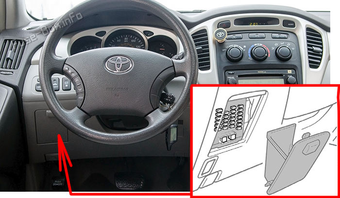
Remove the lid to access.
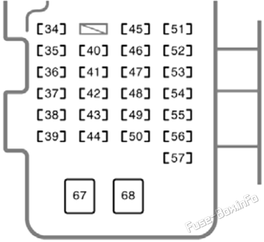
Assignment of the fuses in the instrument panel
№ Name Amp Description 34 IGN 10A Meters and gauges, SRS airbag system, hybrid system, electronically controlled brake system, engine immobilizer system 35 RAD №2 7.5A Audio system, rear seat entertainment system, navigation system, air conditioning system, multiplex communication system 36 CIG 15A Cigarette lighter 37 P RR DOOR 20A Power windows 38 PWR OUTLET1 15A Power outlets (12V DC) 39 FR FOG 20A Front fog lights 40 ECU-IG 10A Electronically controlled brake system, transmission control system, electric power steering system, theft deterrent system 41 WIPER 25A Windshield wipers 42 D RR DOOR 20A Power windows 43 D FR DOOR 25A Power windows, power door lock system, door courtesy light 44 S/ROOF 20A Electric moonroof 45 HEATER 10A Air conditioning system, rear heater system, rear window defogger, hybrid system 46 IG1 7.5A Hybrid system, power door lock system, multiplex communication system, airbag on-off indicator lights, turn signal lights, back-up lights, outside rear view mirror defoggers, auto anti-glare inside rear view mirror, power outlet (115 VAC), seat heaters, navigation system 47 RR WIP 15A Rear window wiper 48 STOP 20A Stop lights, high mounted stoplight, electronically controlled brake system, transmission control system, hybrid system 49 OBD 7.5A On-board diagnosis system 50 SEAT HTR 15A Seat heaters 51 IG2 15A Multiport fuel injection system/sequential fuel injection system, engine ignition system 52 WASHER 20A Windshield washer, rear window washer 53 FUEL OPN 7.5A Fuel filler door opening system 54 FR DEF 20A Windshield wiper deicer, rear view mirror defoggers 55 P FR DOOR 20A Power windows, door courtesy light 56 TAIL 10A Parking lights, tail lights, side marker lights, license plate lights, front fog lights 57 PANEL 7.5A Instrument panel lights 67 AM1 40A Fuses: “ECU-IG”, “WASHER”, “IG1”, “WIPER”, “RR WIP”, “HEATER (10 A)”, “RAD №2” and “CIG” 68 POWER 30A Power seat
Login or Register to view this content
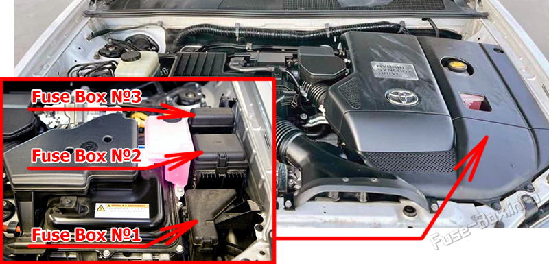
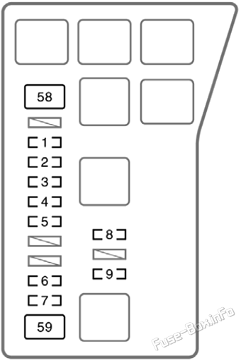
Assignment of the fuses in the Fuse Box No.1
№ Name Amp Description 1 ETCS 10A Hybrid system 2 DC/DC-S 10A Hybrid system 3 ABS №2 10A Electronically controlled brake system 4 ABS №1 10A Electronically controlled brake system 5 BATT FAN 15A Hybrid system 6 ABS №3 15A Electronically controlled brake system 7 OIL PUMP 10A Transmission fluid cooling system 8 ST 7.5A Hybrid system 9 RR HTR 15A Rear heater system 58 ABS MTR2 30A Electronically controlled brake system 59 ABS MTR1 30A Electronically controlled brake system
Login or Register to view this content
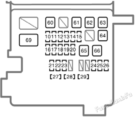
Assignment of the fuses in the Fuse Box No.2
№ Name Amp Description 10 DRL 7.5A Daytime running light system 11 H-LP L LWR 15A Left-hand headlight (low beam) 12 H-LP L UPR 15A Left-hand headlight (high beam) 13 H-LP R UPR 15A Right-hand headlight (high beam) 14 PWR OUTLET №2 20A Power outlet (115V AC) 15 TOWING 20A Trailer lights 16 HAZ 15A Turn signal lights, emergency flashers 17 SECURITY 15A Theft deterrent system 18 AM2 №1 30A Fuses: “IGN”, “IG2” and “ST” 19 MPX-B1 7.5A Electric power steering system 20 HORN 10A Horns 21 RADIO №1 25A Audio system 22 ECU-B №1 7.5A Theft deterrent system, air conditioning system, gauges and meters, electric moonroof, engine immobilizer system, multiplex communication system 23 DOME 10A Personal lights, interior lights, vanity lights, ignition switch light, wireless remote control system, gauges and meters, navigation system 24 DOOR №1 25A Power door lock system 25 A/F 25A Air/fuel control system 26 CRT 7.5A Rear seat entertainment system, navigation system screen 27 H-LP R LWR 15A Right-hand headlight (low beam) 28 INV W/P 15A Hybrid system 29 IGCT №5 10A Hybrid system 60 HEATER 50A Air conditioning system, “WATER PUMP” fuse 61 RR HTR 30A Rear heater system 62 RR DEF 30A Rear window defogger 63 RDI FAN №1 40A Electric cooling fan 64 RDI FAN №2 40A Electric cooling fan 65 MAIN 40A Fuses: “H-LP L LWR”, “H-LP L UPR”, “H-LP R LWR”, “H-LP R UPR” and “DRL” 66 IGCT №1 50A Fuses: “INV W/P”, “IGCT №2”, “IGCT №3”, “IGCT №4” and “IGCT №5” 69 DC/DC 120A Hybrid system
Login or Register to view this content
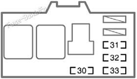
Assignment of the fuses in the Fuse Box No.3
№ Name Amp Description 30 WATER PUMP 10A Air conditioning system 31 IGCT №4 10A Emission control system, transmission control system, air/fuel control system 32 IGCT №3 10A Hybrid system, fuel pump 33 IGCT №2 10A Hybrid system
Login or Register to view this content