In this article, we focus on the first-generation Audi TT (chassis code 8N), a groundbreaking and stylish sports car produced from 1998 to 2006. Recognized for its iconic design, engaging performance, and innovative features, the first-generation TT set the stage for Audi’s success in the luxury coupe and roadster market.
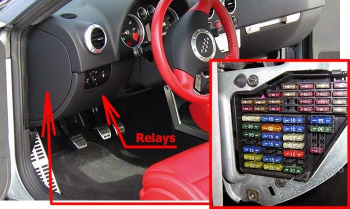
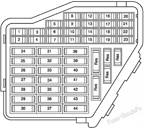
Here, you will find detailed fuse box diagrams for Audi TT models produced in 1998, 1999, 2000, 2001, 2002, 2003, 2004, 2005 and 2006. These diagrams provide valuable insights into the vehicle’s electrical systems, including the assignment of each fuse (fuse layout) and relay. This information is crucial for diagnosing electrical issues, conducting maintenance, or carrying out repairs.
This article serves as a comprehensive guide to the electrical system of the first-generation Audi TT, ensuring that owners have the essential knowledge to maintain the functionality, reliability, and performance of this iconic sports car.
Mobile telephone operating electronics control unit
9
5A
ABS control unit
10
10A/15A
1998-2001: Motronic control unit Motronic current supply relay; 2002-2006: S contact Central locking control unit Control unit in dash panel insert
11
5A
Control unit in dash panel insert Oil level and oil temperature sender
12
7.5A
Diagnosis connection Mobile telephone operating electronics control unit Aerial amplifier for mobile telephone
13
10A
Brake light switch
14
10A
Central locking control unit Door warning lamp, left Door warning lamp, right Interior monitor deactivation switch Interior locking switch, driver’s side Rear lid remote release switch
15
5A
Control unit in dash panel insert Automatic gearbox control unit
16
10A
Radiator fan control unit
17
–
Not used
18
10A
Main beam bulb, right Fog light relay Control unit in dash panel insert
19
10A
Main beam bulb, left
20
15A
Headlight range control motor, right Headlight range control regulator Headlight range control motor, left Bulb monitoring device, front
21
15A
Bulb monitoring device, front
22
5A
Bulb monitoring device, front Side light bulb, right Control unit in dash panel insert
23
5A
Bulb monitoring device, front Side light bulb, left Control unit in dash panel insert
24
20A
Automatic intermittent wash and wipe relay Intermittent wiper switch
25
25A
Ar conditioning system/Climatronic operating and display unit Heated rear window relay Fresh air blower Fresh air blower control unit
26
25A
Heated rear window switch
27
30A
Cabrio windbreak control unit Cabrio windbreak switch
28
20A
Fuel system pressurisation pump
29
15A
Motronic control unit
30
–
Not used
31
5A/20A
Four-wheel drive control unit Automatic gearbox control unit
32
10A
Injectors
33
20A/30A
Automatic intermittent wash and wipe relay
34
10A
Charge pressure control solenoid valve Inlet camshaft control valve 1 Turbocharger air recirculation valve
35
–
Not used
36
15A
Front and rear fog light switch
37
10A/20A
1998-2001 (10A): S contact Central locking control unit Control unit in dash panel insert; 2002-2006 (20A): Motronic control unit Motronic current supply relay
38
15A
Central locking control unit Anti-theft alarm system horn
39
15A
Hazard warning light switch
40
20A
Dual tone horn relay
41
15A
Cigarette lighter
42
20A
Radio Amplifier
43
10A/15A
Activated charcoal filter system solenoid valve 1 Secondary air inlet valve Secondary air pump relay Air mass meter Exhaust gas temperature sender 1
44
15A
Heated driver’s seat regulator Heated front passenger’s seat regulator
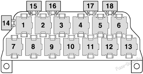
Relays
Fuse Data
Full access is available to registered users — log in or register.
 | 2006-2014 | Fuse Box Diagrams and Locations")
 | 2014-2023 | Fuse Box Diagrams and Locations")