The fourth-generation BMW 5-Series (chassis code E39) , a luxury mid-size sedan and touring model, was produced from 1995 to 2004 . Renowned for its timeless design, exceptional driving dynamics, and advanced features, the E39 remains one of the most iconic and reliable BMW models to date.
In this article, you will find fuse box diagrams for BMW 5-Series models produced between 1995 and 2004 , covering years 1995, 1996, 1997, 1998, 1999, 2000, 2001, 2002, 2003, and 2004 . These diagrams provide essential information about the fuse layout and relay assignments, making it easier to diagnose and maintain your vehicle’s electrical systems.
What’s Included:
Fuse Box Diagrams : Detailed visuals to help identify fuses and relays quickly.Fuse Panel Locations : Clear instructions on where to locate the fuse panels inside the BMW 5-Series.Fuse Assignments : A comprehensive breakdown of each fuse and relay function for simplified troubleshooting and repairs.
Whether you’re a DIY enthusiast or a professional technician, this guide is an invaluable resource for maintaining your BMW 5-Series (E39). From replacing blown fuses to diagnosing electrical issues, this reference ensures you have the tools and knowledge to keep your vehicle running smoothly.
Keep your BMW 5-Series (E39) in top condition with this detailed fuse box guide!
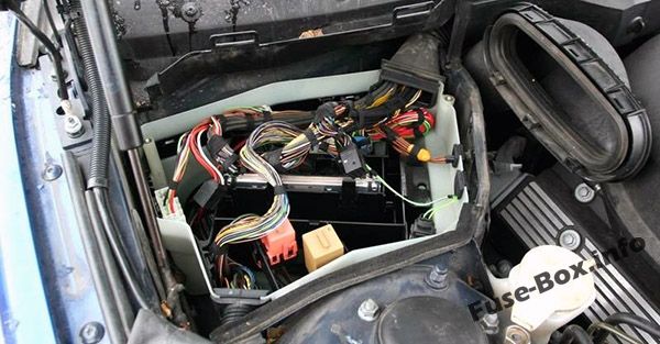
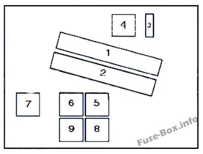
Assignment of the fuses in the engine compartment (type 1)
Fuse Data
Full access is available to registered users — log in or register.
Log in or register
№ Component 1 Engine control module 2 Transmission control module 3 Engine control module fuse 4 Engine control module relay 5 Windscreen wiper motor relay I 6 Windscreen wiper motor relay II 7 Air conditioning condenser blower motor relay I 8 Air conditioning condenser blower motor relay III 9 ABS relay
This content requires JavaScript and a valid membership to view.
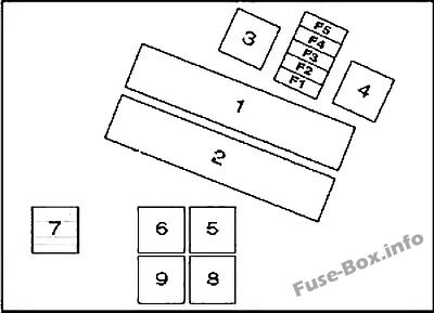
Assignment of the fuses in the engine compartment (type 2)
Fuse Data
Full access is available to registered users — log in or register.
Log in or register
№ A Component 1 Engine control module(ECM) 2 Transmission control module(TCM) 3 Engine control (EC)relay 4 Ignition coil relay- except 520i (22 6S 1)/525i/530i 5 Windscreen wiper motor relay 1 6 Windscreen wiper motor relay2 7 AC condenser blower motor relay 1 (until 03/98) 8 AC condenser blower motor relay 3 (until 03/98) 9 Secondary air injection (AIR) pump relay F1 30A Engine control module(ECM), evaporative emission (EVAP) canister purge valve, mass airflow (MAF) sensor, camshaft position (CMP)sensor1 .engine coolant thermostat-535i/540i F2 30A Secondary air injection (AIR)pump, intake manifold air control solenoid, injectors (except 520i (22 6S1)/525i/530i),engine control module(ECM), evaporative emission (EVAP) canister purge valve, camshaft position (CMP) actuator 1 &2, idle speed control (ISC) actuator F3 20A Crankshaft position (CKP) sensor, camshaft position (CMP)sensorl &2, mass airflow(MAF)sensor F4 30A Heated oxygen sensors(H02S), transmission control module (TCM) F5 30A Ignition coil relay-except 520i (22 6S1)/525i/530i
This content requires JavaScript and a valid membership to view.
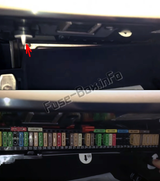
Open the glove compartment, turn the two clamps to the left, and pull the panel down.
Fuse layout may differ! Your exact fuse allocation scheme is located under this fusebox.
Fuse Data
Full access is available to registered users — log in or register.
Log in or register This content requires JavaScript and a valid membership to view.
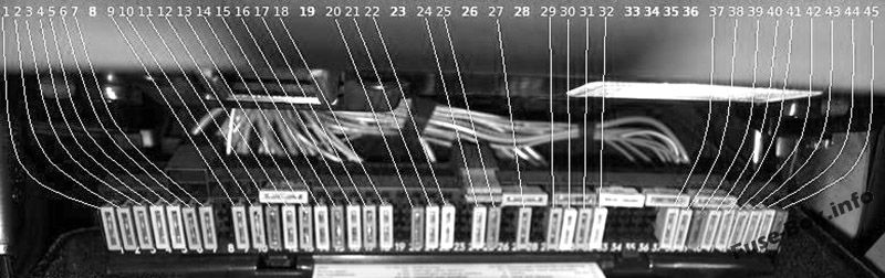
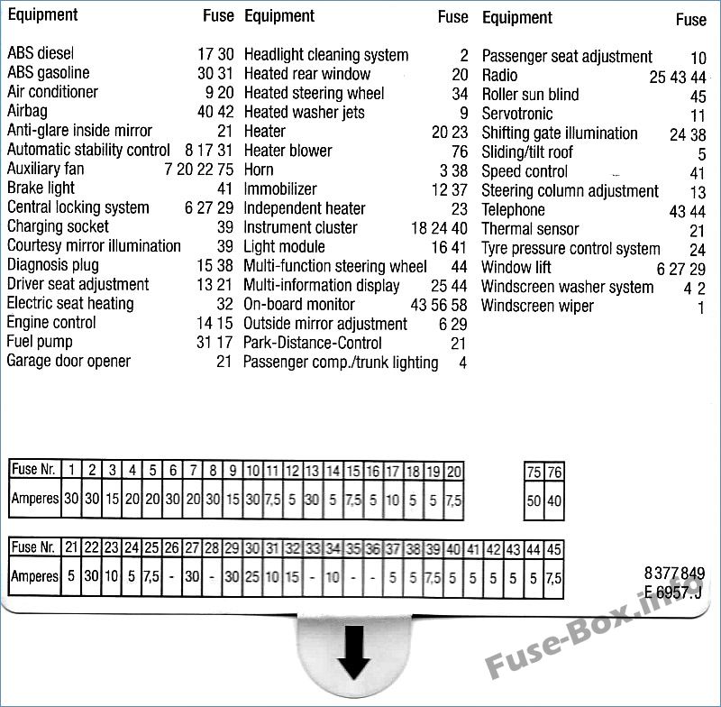
Assignment of the fuses in the glove compartment (until 03.1998)
Fuse Data
Full access is available to registered users — log in or register.
Log in or register
№ A Component F1 30A Windscreen wiper motor relay F2 30A Headlamp washers F3 15A Horn F4 20A Multifunction control module F5 20A/30A Sunroof F6 30A Electric door mirror, passenger’s side F7 20A/30A AC condenser blower motor relay 1 F8 – – F9 15A AC/ heater control module F10 30A Seat adjustment-passenger’s side F11 7,5A Multifunction control module- variable power steering F12 5A Immobilizer F13 30A Seat adjustment-driver’s side, steering column adjustment F14 5A Engine control module (ECM) F15 7,5A Transmission control module (TCM), engine oil level sensor, alternator, electrics box temperature switch (530d) F16 5A Lamps control module F17 10A Fuel pump relay, ABS control module, multi switch assembly F18 5A Instrument panel F19 5A Overvoltage protection relay 2 F20 5A/7.5A AC/heater control module, heated rear window relay, tyre pressure monitor control module F21 5A Cigarette lighter relay, seat adjustment relay/steering column adjustment relay, garage door opener, parking aid control module, anti-dazzle interior mirror F22 30A AC condenser blower motor relay 2 F23 7,5A Digital multifunction display-rear F24 5A Instrument panel, tyre pressure monitor control module, steering position sensor F25 7,5A Digital multifunction display F26 – – F27 30A Multifunction control module F28 15A Automatic transmission (AT) F29 30A Door function control module, driver’s side F30 25A ABS control module F31 10A Fuel pump relay, ABS control module, secondary air injection (AIR) pump relay (petrol) F32 25A Multi switch assembly F33 – – F34 10A Multifunction steering wheel/airbag assembly, heated steering wheel F35 5A AC condenser blower motor, rear F36 – – F37 5A Immobilizer control module F38 5A Multifunction control module, horn relay, rain sensor, transmission shift hold switch (AT), data link connector (DLC) F39 7,5A Vanity mirror lamps, rechargeable torch F40 5A Instrument panel, seat adjustment control module, airbag crash sensor, seat belt contact switch (drivers side) F41 5A Lamps control module, clutch pedal position (CPP) switch, brake pedal position (BPP)switch F42 5A SRS control module F43 5A Over voltage protection relay 1 F44 5A Multifunction steering wheel/airbag assembly, steering wheel, digital multifunction display-frontfrear F45 7,5A Multi switch assembly
This content requires JavaScript and a valid membership to view.
Assignment of the fuses in the glove compartment (since 03.1998)
Fuse Data
Full access is available to registered users — log in or register.
Log in or register
№ A Component F1 30A Windscreen wiper motor relay F2 30A Headlamp washers F3 15A Horn F4 20A Multifunction control module F5 20A/30A Sunroof F6 30A Electric door mirror, passenger’s side F7 20A/30A Cigarette lighter-front (09/00) F8 – – F9 15A AC/heater control module F10 30A Seat adjustment-passenger’s side F11 7,5A Multifunction control module- variable power steering F12 5A Immobilizer F13 30A Seat adjustment-driver’s side, steering column adjustment F14 5A Engine control module (ECM) F15 7,5A Transmission control module (TCM), engine oil level sensor, alternator, electrics box temperature switch (530d) F16 5A Lamps control module F17 10A Fuel pump relay, ABS control module, multi switch assembly F18 5A Instrument panel F19 5A Overvoltage protection relay 2 F20 5A/7.5A AC/heater control module, heated rear window relay, tyre pressure monitor control module F21 5A Cigarette lighter relay, seat adjustment relay/steering column adjustment relay, garage door opener, parking aid control module, anti-dazzle interior mirror F22 25A Fuel pumprelay-530d/520i(226S1)/525i/530i F23 7,5A Digital multifunction display-rear F24 5A Instrument panel, tyre pressure monitor control module, steering position sensor F25 7,5A Digital multifunction display F26 – – F27 30A Multifunction control module F28 15A Automatic transmission (AT) F29 30A Door function control module, driver’s side F30 25A ABS control module F31 10A Fuel pump relay, ABS control module, secondary air injection (AIR) pump relay (petrol) F32 25A Multi switch assembly F33 – – F34 10A Multifunction steering wheel/air bag assembly, heated steering wheel F35 5A AC condenser blower motor, rear F36 – – F37 5A Immobilizer control module F38 5A Multifunction control module, horn relay, rain sensor, transmission shift hold switch (AT), data link connector (DLC) F39 7,5A Vanity mirror lamps, rechargeable torch F40 5A Instrument panel, seat adjustment control module, airbag crash sensor, seat belt contact switch (driver’s side) F41 5A Lamps control module, clutch pedal position(CPP) switch, brake pedal position (BPP)switch F42 5A SRS control module F43 5A Overvoltage protection relay 1 F44 5A Multifunction steering wheel/air bag assembly, steering wheel, digital multifunction display-front/rear F45 7,5A Multi switch assembly
This content requires JavaScript and a valid membership to view.
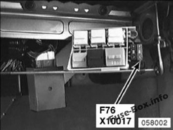
It is located behind the fuse box.
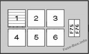
Assignment of the relays
Fuse Data
Full access is available to registered users — log in or register.
Log in or register
№ component 1 AC condenser blower motor relay 2(until 03/98) 2 Headlamp washer pump relay 3 – 4 Starter motor relay 5 Seat adjustment relay/steering column adjustment relay 6 Heater blower relay F75 (50A) AC condenser blower motor/engine coolant blower motor F76 (40A) AC/heater blower control module
This content requires JavaScript and a valid membership to view.
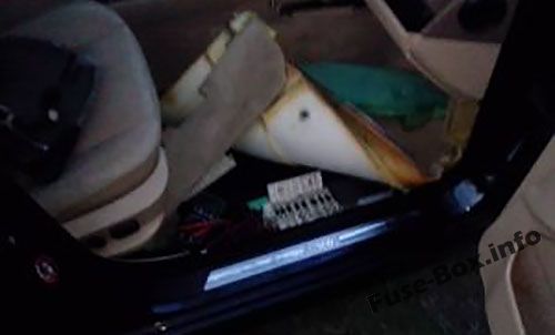
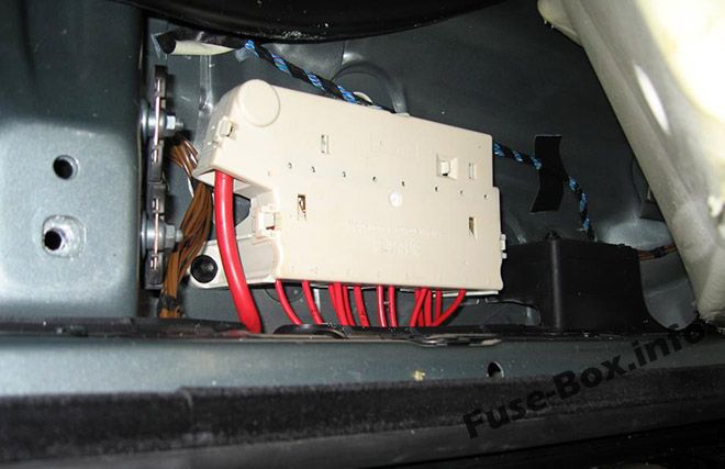
Block in the footwell
It is located on the floor under the lining, on the right side of the car.
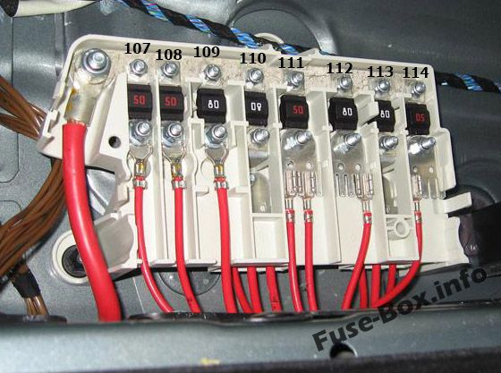
Assignment of the fuses (footwell)
Fuse Data
Full access is available to registered users — log in or register.
Log in or register
№ A Component F107 50A Secondary air injection (AIR) pump relay F108 50A ABS control module F109 80A Engine control (EC) relay, fuse box-engine bay (F4&F5) F110 80A Fuse box-fascia 1 (F1-F12&F22-F25) F111 50A Ignition switch F112 80A Lamps control module F113 80A Seat adjustment relay/steering column adjustment relay, fuse box-fascia 1 (F27-F30), fuse box-fascia 2 (F76), lamps control module, fuse box-fascia 1 (F13)-with lumbar support F114 50A Ignition switch, data link connector (DLC)
This content requires JavaScript and a valid membership to view.
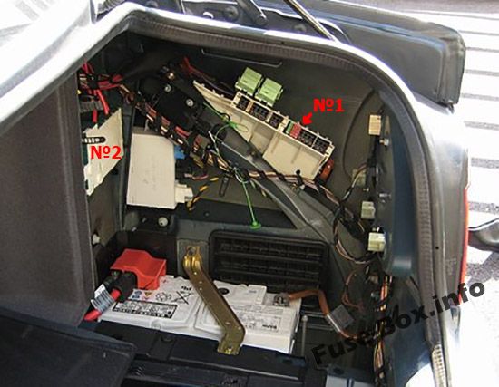
They are located on the right side, behind the cover.
Fuse layout may differ! Your exact fuse allocation scheme is located on the cover.
Fuse Data
Full access is available to registered users — log in or register.
Log in or register This content requires JavaScript and a valid membership to view.
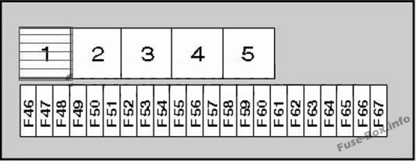
Assignment of the fuses and relay (box 1, type 1)
Fuse Data
Full access is available to registered users — log in or register.
Log in or register
№ A Component 1 Overvoltage protection relay 1 2 Fuel pump relay 3 Heated rear window relay 4 Overvoltage protection relay 2 5 Fuel filler flap relay F46 – – F47 15A/20A Auxiliary heater F48 5A Anti-dazzle interior mirror, alarm system in car movement control module, alarm system gradient sensor, alarm system horn F49 30A Suspension compressor relay F50 7,5A Suspension control module (with air suspension) F51 30A Cigarette lighter- rear F52 30A Cigarette lighter relay, cigarette lighter-front F53 5A Aerial signal amplifier, boot lid/tail gate lockstitch F54 15A Fuel pump relay F55 20A Rear screen wash/wipe relay F56 30A Audio unit, navigation system control module, audio unit output amplifier, audio unit CD changer, in-car monitor F57 10A Telephone F58 10A Overvoltage protection relay 1 F59 20A Trailer socket F60 15A Suspension control module, multi switch assembly F61 25A Rear seat heater switch, left, rear seat heater switch, right F62 – – F63 – – F64 – – F65 – – F66 40A Heated rear window relay F67 – –
This content requires JavaScript and a valid membership to view.
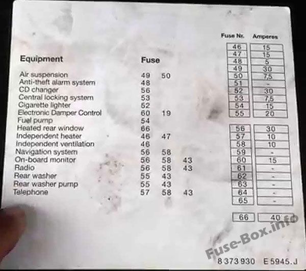
Assignment of the fuses and relay (box 1, type 2)
Fuse Data
Full access is available to registered users — log in or register.
Log in or register
№ A Component 1 Ignition main circuits relay 2 Fuel pump relay 3 Heated rear window relay 4 Ignition auxiliary circuits relay 5 Independent heater relay F46 15A independent heater/ventilation F47 15A independent heater F48 5A Alarm system F49 30A Air suspension system F50 7,5A Air suspension system F51 – – F52 30A Cigarette lighter F53 7,5A Central locking system F54 15A Fuel pump F55 – – F56 30A Audio system, navigation system, on-board monitor F57 10A Cellular phone F58 10A Audio unit, on-board monitor, navigation system, telephone F59 – – F60 15A Suspension adjustment control F61 – – F62 – – F63 – – F64 – – F65 – – F66 40A Heated rear window F67 – – F6S – – F69 – – F70 – – F71 – – F72 – – F73 – – F74 – –
This content requires JavaScript and a valid membership to view.
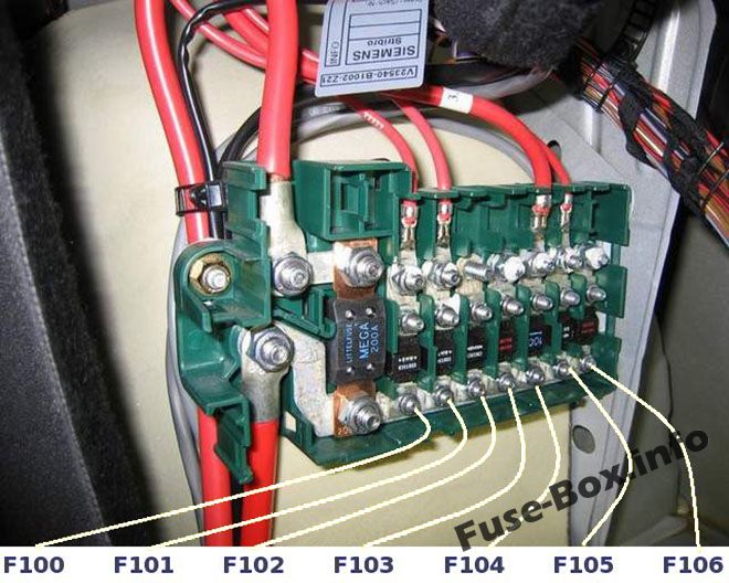
Assignment of the fuses and relay (box 2)
Fuse Data
Full access is available to registered users — log in or register.
Log in or register
№ A Component F100 200A Fuse box-footwall (F107-F114) F101 80A Fuse box – load area 1 (F46-F50, F66) F102 80A Fuse box-load area 1 (F51-F55) F103 50A Trailer control module F104 50A Overvoltage protection relay 2 F105 100A Fuse box-fascia 2 (F75), auxiliary heater F106 80A Fuse box-load area 1 (F56-F59)
This content requires JavaScript and a valid membership to view.
 | 2003-2010 | Fuse Box Diagrams and Locations")
 | 2010-2016 | Fuse Box Diagrams and Locations")