The third-generation BMW X5 (chassis code F15) , a luxury mid-size SUV, was produced from 2013 to 2018 . Known for its refined design, advanced technology, and powerful performance, the F15 model solidified the X5’s reputation as a leader in the premium SUV market.
In this article, you will find fuse box diagrams for BMW X5 (Mk3) models produced between 2013 and 2018 , covering years 2013, 2014, 2015, 2016, 2017, and 2018. These diagrams provide critical information about the fuse layout and relay assignments, helping owners and technicians maintain and troubleshoot the vehicle’s electrical systems.
What’s Included:
Fuse Box Diagrams : Detailed and easy-to-read visuals for identifying fuses and relays.Fuse Panel Locations : Clear instructions on where to locate the fuse panels inside the BMW X5.Fuse Assignments : Comprehensive descriptions of the function of each fuse and relay to assist with diagnostics and repairs.
Whether you’re a BMW X5 (F15) owner or a professional mechanic, this guide is an invaluable resource for maintaining the electrical functionality of your vehicle. From replacing fuses to resolving electrical issues, this reference ensures your X5 remains in peak condition.
Keep your BMW X5 (F15) running smoothly with this thorough fuse box guide!
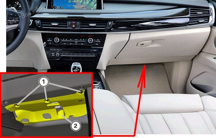
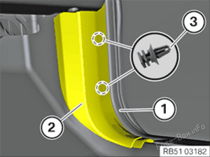
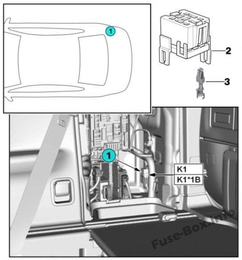
It is located under the glove compartment. Loosen fasteners (1), arrows, carefully remove trim panel, and disconnect respective plug connection.
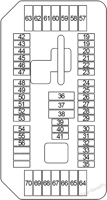
Assignment of the fuses in the Instrument panel
Fuse Data
Full access is available to registered users — log in or register.
Log in or register
№ Amps Protected Component 19 5A Remote Control Receiver 20 5A Roof Function Control Centre 21 5A Preheating Control Unit 22 7.5A Driver’s Door Switch Block, Passenger Exterior Mirror 23 10A Digital Motor Electronics (DME) 24 10A Electronic Transmission Control 25 5A Touchbox, iDrive Controller 26 5A Extendible Dashboard Speaker, Rear Left/Right Seat Heating Switch 27 10A Driver/Passenger Lumbar Support Valve Block, Driver’s/Passenger’s Side Seat Adjustment Switch 28 5A Rain/Light/Solar/Condensation Sensor, Roof Function Control Centre, Vanity Mirror Lights 29 15A Auxiliary Water Pump 30 10A Coolant Pump for Charge Air Cooler 31 5A Electric Fan Cut-Out Relay 32 5A Transfer Box 33 5A N63, S63: Turbocharger Coolant Pump 34 5A Integrated Chassis Management (ICM) 35 5A Electrochromic Interior Rear View Mirror 36 20A Centre Power Socket (12V Connection) 37 20A Front Cigarette Lighter (12V Connection) 38 20A Roof Function Control Centre 39 15A Left Headlight 40 – – 41 10A S63: Coolant Pump for Charge Air Cooler 42 5A Electronic Damper Control, Electrochromic Interior Rear View Mirror 43 5A Left/Right Targeted Illumination 44 7.5A Camera-Based Driver Assistance Systems (KAFAS), Active Steering 45 5A Active Cruise Control (ACC), Automatic Air Recirculation Control Sensor (AUC) 46 5A Radiator Shutter Drive Unit 47 5A Electronic Night Vision Module (NVE), Vehicle Sound Generator (VSG) 48 10A Steering Column Switch Center 49 5A Steering Angle Sensor 50 5A Instrument Cluster 51 – – 52 7.5A Instrument Cluster 53 5A Glove Compartment Light, Decor Strip Lighting, Door Pocket Lighting, Door Panel Lighting, Front Left/Right Footwell Light 54 10A Gear Selector Switch (GWS) 55 5A Servotronic (SVT), Electromechanical Power Steering (EPS) 56 5A Vertical Dynamics Management (VDM) 57 20A Left Headlight 58 30A Dynamic Stability Control (DSC) 59 40A Active Steering 60 40A Blower Output Stage 61 20A Electronic Damper Control 62 20A/30A Vertical Dynamics Management (VDM) 63 30A Transfer Box (VTG) 64 30A Passenger’s Seat Heating Module 65 30A Driver’s Seat Heating Module 66 20A Independent Auxiliary Heater 67 30A Driver’s Side Seat Adjustment Switch Block (without Seat Module (SMFA)), Driver Seat Module (SMFA) 68 30A Passenger’s Side Seat Adjustment Switch Block (without Seat Module (SMBF)), Passenger’s Seat Module (SMBF) 69 20A Electronic Transmission Control (EGS) 70 20A Electric Steering Column Adjustment
This content requires JavaScript and a valid membership to view.
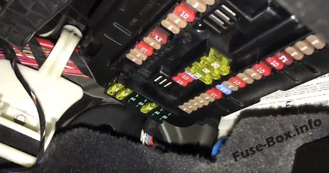
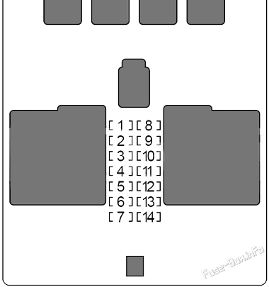
It is located in the front pillar on the passenger side, behind the cladding, under the glove box.
Detach edge protection (1) in area of side trim panel (2). Release side trim panel (2) from clips (3) with special tool 00 9 325 and remove. If necessary, lever out clamps (3) remaining in bore holes.
Assignment of the fuses
Fuse Data
Full access is available to registered users — log in or register.
Log in or register
№ Amps Protected Component 1 30A Passenger Power Window Drive 2 30A Driver’s Side Rear Power Window Drive 3 20A Front Passenger Door Lock 4 30A Driver Power Window Drive 5 30A Rear Window Defogger 6 30A Passenger’s Side Rear Power Window Drive 7 20A Driver’s Door Lock 8 – – 9 5A Steering Column Switch Center, Light Switch Unit, Driver Assistance System Operating Facility with Hazard Warning Switch 10 7.5A Left Headlight 11 7.5A Diagnostic Connector, Heating/Air Conditioning System, Dynamic Stability Control (DSC) 12 5A Telematic Communication Box, Electronic Outer Doors Handles Module 13 15A Horn (Low/High Range) 14 – –
This content requires JavaScript and a valid membership to view.
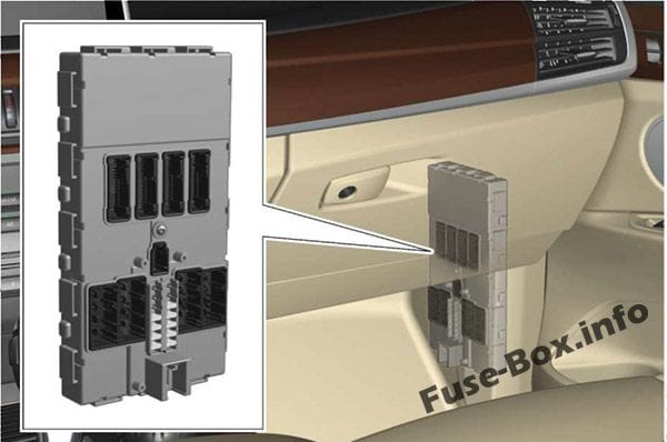
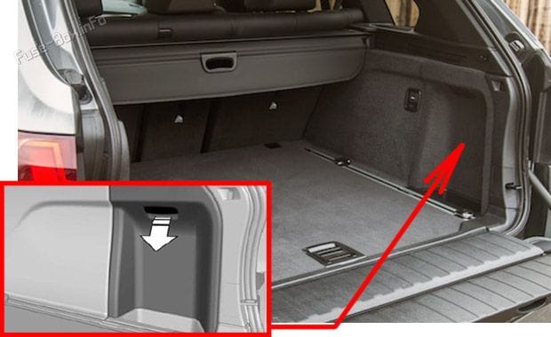
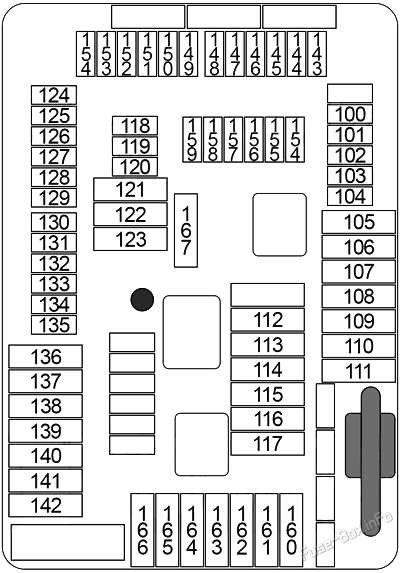
It is located on the right side, behind the cover. Open the cover on the right side trim, arrow.
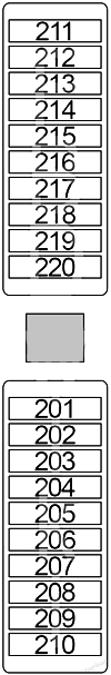
Assignment of the fuses in the luggage compartment
Fuse Data
Full access is available to registered users — log in or register.
Log in or register
№ Amps Protected Component 100 5A Parking Brake Button 101 15A Right Headlight 102 5A High-Voltage Battery Unit 103 5A Siren with Tilt Alarm Sensor 104 5A Parking Brake Control Unit, Natural Vacuum Leak Detection (NVLD) 105 30A Reversible Electromotive Automatic Reel (Right) 106 30A Rear Axle Lateral Torque Distribution 107 40A Automatic Luggage Compartment Lid Actuation (2014-2016), Tailgate Function Module (2016-2019) 108 – – 109 – – 110 40A Air Suspension Compressor Relay 111 – – 112 20A Pressurised Fuel Tank Control Module 113 30A Trailer Module 114 30A Trailer Module 115 20A Right Headlight 116 30A Parking Brake Control Unit 117 30A Reversible Electromotive Automatic Reel (Left) 118 5A Video Switch (VSW) 119 – – 120 5A Power Control Unit 121 20A Headunit 122 30A Audio Amplifier 123 – – 124 5A Video Module 125 – – 126 10A Rear Passenger’s Door Automatic Soft-Close Drive 127 5A DVD-Changer 128 5A Wireless Charging Oddments Tray, Antenna Amplifier, Base Plate 129 15A Active Sound Design (ASD) 130 5A Automatic Luggage Compartment Lid Actuation 131 5A Luggage Compartment Light, Rear Lid Button on Inside of Rear Lid, Noise Suppressor Filter 132 5A Rear Axle Lateral Torque Distribution, Electronic Ride Height Control 133 5A Rear Compartment Automatic Climate Control 134 5A Rear Driver’s Door Automatic Soft-Close Drive 135 5A Safety Battery Terminal Gas Generator 136 – – 137 – – 138 – – 139 20A Trailer Socket 140 20A Boot Lid/Tailgate Lock 141 – – 142 – – 143 10A Cool Box Relay 144 15A Selective Catalytic Reduction (SCR) Control Unit 145 5A Parking Assistant, Infotainment Fan №2 146 15A Electrical Exhaust Flap (№1, №2) 147 15A Selective Catalytic Reduction (SCR) Control Unit 148 5A Lane Change Warning (SWW) 149 7.5A Right Headlight 150 5A 2014-2016: Contact-Free Tailgate Opening Evaluation Electronics, Convenience Charging Electronics 150 7.5A 2016-2019: Contact-Free Tailgate Opening Evaluation Electronics, Convenience Charging Electronics, Tailgate Function Module 151 5A USB-HUB (USB Connection №1/№2, AUX-In Connection) 152 5A Reversible Electromotive Automatic Reel (Left/Right) 153 15A Selective Catalytic Reduction (SCR) Control Unit 154 5A All-Round Vision Camera (TRSVC), Reversing Camera 155 10A Passenger’s Door Automatic Soft-Close Drive 156 10A Driver’s Door Automatic Soft-Close Drive 157 – – 158 10A Rear Seat Entertainment 159 5A Audio Amplifier, Infotainment Fan №2 160 20A Rear Compartment Blower Motor 161 – – 162 20A Rear Cigarette Lighter (12V Connection №1 & №2), Luggage Cigarette Lighter (12V Connection) 163 30A Trailer Module 164 30A Right Rear Seat Heating Module 165 20A Fuel Pump Control (EKPS) 166 30A Left Rear Seat Heating Module 167 30A Driver’s Door Automatic Soft-Close Drive, Passenger’s Door Automatic Soft-Close Drive
This content requires JavaScript and a valid membership to view.
It can be located near the fuse box, for example a pneumatic suspension relay or a refrigerator relay.
Assignment of the fuses
Fuse Data
Full access is available to registered users — log in or register.
Log in or register
№ Amps Protected Component 201 10A Auxiliary Control Unit (SEC) 202 7.5A Auxiliary Control Unit (SEC) 203 5A Auxiliary Control Unit (SEC) 204 5A Auxiliary Control Unit (SEC) 205 5A Switch Cluster Auxiliary Module 206 5A Audio Auxiliary Module 207 20A Audio Auxiliary Module 208 5A Audio Auxiliary Module 209 5A Audio Auxiliary Module 210 5A Auxiliary Control Unit (SEC) 211 20A Windscreen Defogger 212 20A Windscreen Defogger 213 15A Heated Side Window (Front Left/Right) 214 5A Auxiliary Control Unit 215 5A Auxiliary Control Unit 216 5A Auxiliary Control Unit 217 5A Audio Auxiliary Module 218 5A Auxiliary Control Unit 219 5A Audio Auxiliary Module 220 5A Auxiliary Control Unit
This content requires JavaScript and a valid membership to view.
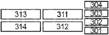
Assignment of the fuses
Fuse Data
Full access is available to registered users — log in or register.
Log in or register
№ Amps Protected Component 301 10A Auxiliary Control Unit 302 5A Switch Cluster Auxiliary Module 303 5A Audio Auxiliary Module 304 5A Auxiliary Control Unit (SEC) 311 30A Power Window 312 30A Power Window 313 30A Power Window 314 30A Power Window 615 5A Electric-Machine Electronics (EME) 612 – –
This content requires JavaScript and a valid membership to view.
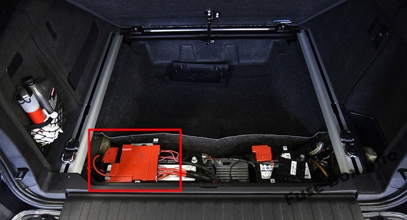
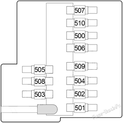
It is located in the luggage compartment, under the lining. Here are high-power fuses for protect the entire circuit.
Assignment of the fuses
Fuse Data
Full access is available to registered users — log in or register.
Log in or register
№ Amps Protected Component 500 50A Body Domain Controller (BDC) 501 125A Rear Power Distribution Box 502 150A Dynamic Stability Control (DSC) 503 125A N63, S63, N20: Integrated Supply Module 504 125A Body Domain Controller (BDC) 505 50A Audio Amplifier 506 60A N55, N63, S53, B47, N47, N57: Power Control Unit (PCU) 507 40A Rear Right Electric Auxiliary Heater 508 40A 3rd Seat Row Auxiliary Heating Control 509 40A Body Domain Controller (BDC) 510 40A Rear Left Electric Auxiliary Heater
This content requires JavaScript and a valid membership to view.
 | 1999-2007 | Fuse Box Diagrams and Locations")
 | 2007-2013 | Fuse Box Diagrams and Locations")
 | 2019-2025 | Fuse Box Diagrams and Locations")