Looking for Buick Envision fuse box diagrams ? This article covers the second-generation Buick Envision after a facelift , available from 2024 , and includes fuse box diagrams for Buick Envision 2024, 2025 and 2026 , along with details about the location of the fuse panels inside the vehicle and a clear explanation of the assignment of each fuse and relay (fuse layout).
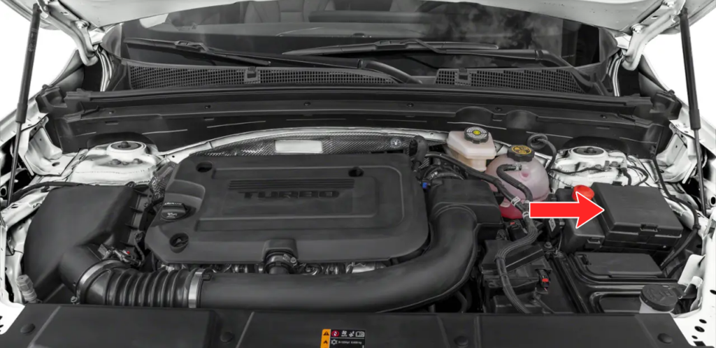
To remove the fuse block cover, squeeze the clips on the cover and lift it straight up.
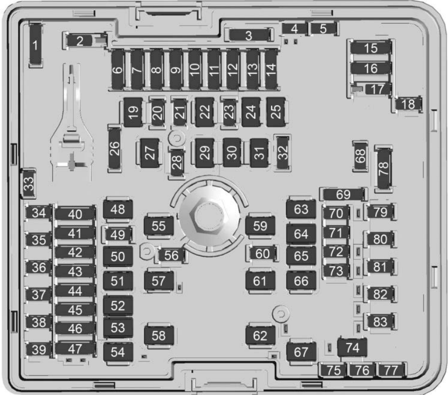
Assignment of the fuses in the engine compartment
Fuse Data
Full access is available to registered users — log in or register.
Log in or register
No. Usage F01 SPARE F02 AERO_SHUT – Aeroshutter F03 SPARE F04 SPARE F05 SPARE F06 – F07 ECM MAIN – Engine Control Module Main F08 ECM PT IGN2 – Engine Control Module Ignition 2 F09 ECM&IGN COIL – Engine Control Module & Ignition Coil F10 SPARE F11 WRAF/STEP CAM/APMB/ EVAPP – Wide-range Air Fuel Oxygen Sensor/ Step Cam Intake/Step Cam Exhaust/Blower Accessory Power Module/ Evaporative Emission Purge Pump F12 SPARE F13 ECM_V_BATT – Engine Control Module Battery F14 SPARE F15 – F16 – F17 A/C CONTROL – Air Conditioning Control F18 SPARE F19 STARTER_PINION – Starter Pinion F20 SPARE F21 SPARE F22 SPARE F23 CWP – Charge Air Coder Water Pump F24 SPARE F25 STRTR_MTR – Starter Motor F26 SPARE F27 SPARE F28 – F29 SPARE F30 – F31 SPARE F32 – F33 SPARE F34 ELM_7 – Exterior Lighting Module7 F35 HEADLAMP_LEFT F36 ELM_BAT3 – Exterior Lighting Module 3 F37 ELM_BAT5 – Exterior Lighting Module 5 F38 HEADLAMP_RIGHT F39 SPARE F40 DOOR PANEL SW – Door Panel Switch F41 MSM DRVR/PASS – Memory Seat Module Driver/Passenger F42 HFRC – Hands Free Closure Release F43 FRT_HTD_SEAT – Front Heated Seat F44 AUTOMATIC LIGHTING/RFR F45 REAR_SEAT – Rear Heated Seat F46 SOLENOID_Canister Vent – Canister Vent Solenoid F47 RDCM_2 – Rear Drive Control Module 2 F48 DC_DC – Direct Current to Direct Current Converter F49 SPARE F50 MTR WDO LIFTER LT – Left Window Lifter Motor F51 RDCM_1 – Rear Drive Control Module 1 F52 PASS/PWR/SEAT – Passenger Power Seat F53 SPARE F54 DRVR/PRW/SEAT – Driver Power Seat F55 SPARE F56 TRLR PRK LAMP – Trailer Park Light F57 SPARE F58 SPARE F59 EBCM_1 – Electronic Brake Control Module 1 F60 HORN F61 REAR DEFOG F62 FRT/WPR – Front Wiper F63 PWR_LGATE – Power Tailgate F64 MTR_WDW_LIFTER_RT – Right Window Lifter Motor F65 SPARE F66 SUNROOF MTR – Sunroof Motor F67 SPARE F68 SPARE F69 – F70 REAR/WPR – Rear Wiper F71 ELM_4 – Exterior Lighting Module 4 F72 FTZM – Fuel Tank Zone Module F73 SPARE F74 SPARE F75 SPARE F76 SPARE F77 SPARE F78 TRLRST/TRN RT/LT – Trailer Stop Lights/Trailer Turn Right/Left F79 TCM – Transmission Control Module F80 SPARE F81 SADS – Suspension Control Semi-Active Damper System Module F82 – F83 WASH PUMP
This content requires JavaScript and a valid membership to view.
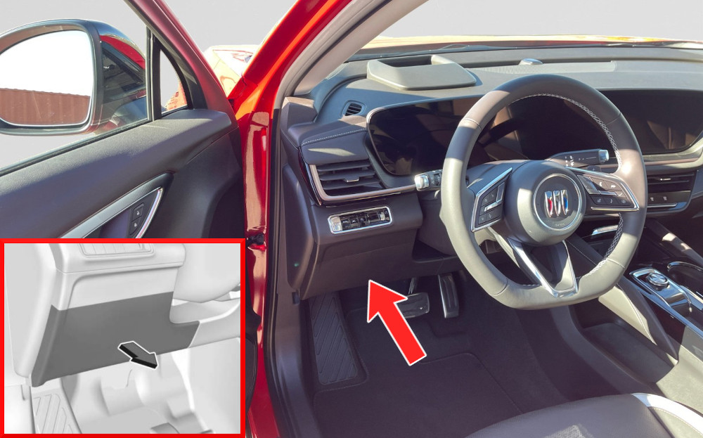
The instrument panel fuse block is on the driver side of the instrument panel, between the steering wheel and the door. To access the fuses, remove the panel, starting at the top. Once clips are disengaged, the tabs along the bottom of the door can be disengaged from the instrument panel to remove the door.
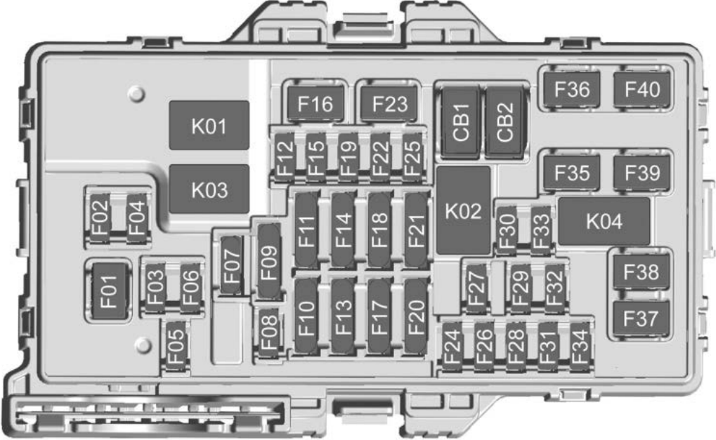
Assignment of the fuses in the passenger compartment
Fuse Data
Full access is available to registered users — log in or register.
Log in or register
No. Usage F01 Blower Motor F02 ACP3 F03 HSWM – Heated Steering Wheel Module F04 ELM 2 – Exterior Lighting Module 2 F05 – F06 – F07 SWC – Steering Wheel Control F08 Auxiliary Audio/Video F09 ESM/BCM_1 – Electronic Shift Module/Body Control Module 1 F10 TAIL_LH/TH F11 VCD/HUD F12 – F13 DLC_WCM – Data Link Connector Wireless Charging Module F14 Headlight F15 ECM/TCM – Electronic Control Module/Telematics Control Module F16 Power Outlet F17 Safety 1&2 F18 EBCM_RC- Electronic Brake Control Module Run/Crank F19 MICROBAS_RC F20 TCP – Telematics Control Platform F21 VCU_BAT – Virtual Cockpit Unit Battery F22 SDM – Sensing Diagnostic Module F23 – F24 OHC – Overhead Console F25 HVAC – Heating, Ventilation, and Air Conditioning F26 ELM 1 – Exterior Lighting Module 1 F27 HVAC Display F28 ELM 6 – Exterior Lighting Module 6 F29 BSM – Battery Status Module F30 – F31 BCM3 – Body Control Module 3 F32 SDM – Sensing Diagnostic Module F33 – F34 Audio Amplifier – UQG F35 Audio Amplifier – UQS F36 DC/DC2 F37 DC/AC Inverter F38 – F39 BCM4 – Body Control Module 4 F40 BCM2 – Body Control Module 2
This content requires JavaScript and a valid membership to view.
Assignment of the circuit breakers in the passenger compartment
Fuse Data
Full access is available to registered users — log in or register.
Log in or register
No. Description CB01 Power Outlet AUX DC ROW1 CB02 –
This content requires JavaScript and a valid membership to view.
Assignment of the relays in the passenger compartment
Fuse Data
Full access is available to registered users — log in or register.
Log in or register
No. Description K01 RAP/ACCY – Retained Accessory Power K02 – K03 Run/Crank K04 –
This content requires JavaScript and a valid membership to view.