Looking for Buick Envista fuse box diagrams ? This article covers the first-generation Buick Envista (Model Code: 9BQB) , available from 2024 , and includes fuse box diagrams for Buick Envista 2024, 2025 and 2026 , along with details about the location of the fuse panels inside the vehicle and a clear explanation of the assignment of each fuse and relay (fuse layout).
To remove the fuse block cover, squeeze the clip and lift it up.
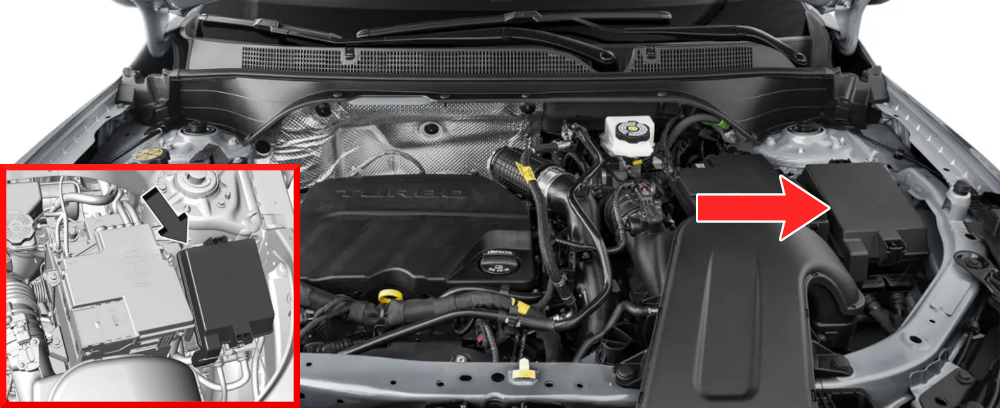
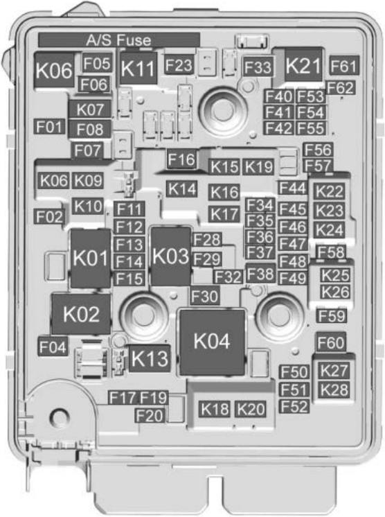
Assignment of the fuses in the engine compartment
Fuse Data
Full access is available to registered users — log in or register.
Log in or register
No. Type Usage F01 Micro L/GATE RELEASE – Liftgate Release F02 Micro A/C CLUTCH – Air Conditioning Clutch F06 Micro HTD OSRVM – Heated Outside Rear View Mirror F08 Micro HORN F10 Micro – F11 Micro ECM PT1 – Electronic Control Module Powertrain 1 F12 Micro IGNITION COIL F13 Micro ENG COMPONENT2 F14 Micro ENG COMPONENT1 F15 Micro ECM PT 2 – Electronic Control Module Powertrain 2 F16 Micro – F17 Micro – F18 Micro RVC F19 Micro ECM BATT – Electronic Control Module Battery F20 Micro AUX WATER PUMP – Auxiliary Water Pump F21 Micro PEPS F24 Micro HTD/SEAT1 F25 Micro HTD/SEAT2 F28 Micro CAC SHUTTER F29 Micro – F31 Micro FTZM – Fuel Tank Zone Module F32 Micro TCM BATT – Traction Control Module Battery F34 Micro ESCLRUN/CRANK – Electric Steering Column Lock Run/Crank F35 Micro – F36 Micro – F37 Micro ECM TCM RUN/CRANK – Electronic Control Module Traction Control Module Run/Crank F40 Micro – F41 Micro HDLP LEVELING – Headlight Leveling F42 Micro CLUSTER F44 Micro WASH PUMP F45 Micro – F46 Micro – F47 Micro CNSTR VENT SOL – Canister Vent Solenoid F48 Micro – F49 Micro REAR WIPER PARK F50 Micro – F51 Micro – F52 Micro – F53 Micro VENT SEAT F54 Micro – F55 Micro – F56 Micro ISRVM/RLAD – Inside Rear View Mirror / Reflective LED Alert Display F57 Micro – F58 Micro REAR WIPER F59 Micro – F62 Micro LUMBAR F03 M-Case STARTER SOL F04 M-Case – F05 M-Case RR DEFOG F07 M-Case COOLING FAN MID F09 M-Case – F22 M-Case FRONT WIPER F23 M-Case – F26 M-Case COOLING FAN LOW F27 M-Case – F30 M-Case – F33 M-Case – F38 M-Case EBCM 2 – Electronic Brake Control Module 2 F39 M-Case COOLING FAN HIGH F43 M-Case – F60 M-Case POWER WINDOW LT F61 M-Case POWER WINDOW RT
This content requires JavaScript and a valid membership to view.
Assignment of the relays in the engine compartment
Fuse Data
Full access is available to registered users — log in or register.
Log in or register
No. Description K01 STARTER SOL RELAY K02 – K03 POWERTRAIN RELAY K04 COOLING FAN HIGH RELAY
This content requires JavaScript and a valid membership to view.
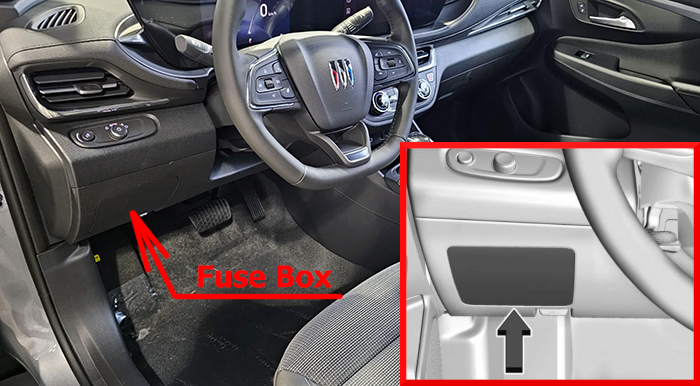
The instrument panel fuse block is on the underside of the driver side instrument panel. To access the fuses, remove the storage compartment. To remove the storage compartment, open the compartment and pull it out.
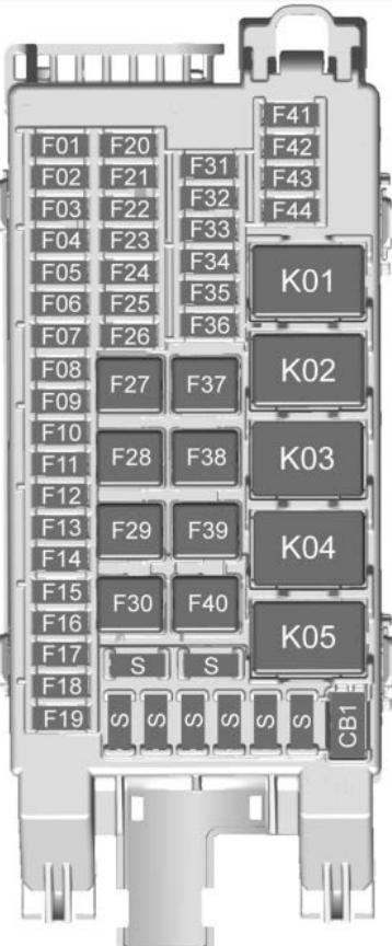
Assignment of the fuses in the instrument panel
Fuse Data
Full access is available to registered users — log in or register.
Log in or register
No. Usage F01 ONSTAR for NA market F02 Sunshade Motor F03 Body Control Module 3 F04 Body Control Module 7 F05 Body Control Module 6 F06 HVAC Module 1 F07 CCM – Central Gateway Module F08 HSWM – Heated Steering Wheel Module F09 Virtual Cockpit Display / Instrument Panel Display / HVAC Display F10 Radio / Virtual Cockpit Unit Module F11 ONSTAR for Non-NA market F12 Side Blind Zone Alert Module / Camera Module / Ultrasonic Park Assist Module F13 HVAC Module IGN F14 Wireless Charger Module / Remote Electronic PRNDL Display F15 BCM2 – Body Control Module 2 F16 BCM1 – Body Control Modulel F17 Steering Wheel Controls Backlighting F18 – F19 – F20 Steering Wheel Controls Switch F21 BCM5 – Body Control Module 5 F22 DLC – Data Link Connector F23 SDM – Sensing Diagnostic Module F24 Discrete Logic Ignition Switch F25 PTM1 – Power Tailgate Modulel F26 Logistic F27 – F28 BCM8 – Body Control Module8 F29 DC to DC Converter 2 F30 PTM 2 – Power Tailgate Module 2 (Motor) F31 OSRVM/ETC/Rain Light Humidity Sensor/ Humidity Sensor F32 Headlight Low Beam Light LEFT F33 BCM 4 – Body Control Module 4 F34 Headlight Low Beam Light RIGHT F35 – F36 – F37 Seat Position Switch DRIVER F38 DC to DC Converter 1 F39 ACC/RAP Relay/RUN Relay F40 Blower Motor Control Module F41 Auxiliary Audio/Video Jack / FRT USB F42 Auxiliary RR USB Power Outlet F43 – F44 – S Spare fuses
This content requires JavaScript and a valid membership to view.
Assignment of the circuit breakers in the instrument panel
Fuse Data
Full access is available to registered users — log in or register.
Log in or register
No. Description CB1 Auxiliary DC Power Outlet
This content requires JavaScript and a valid membership to view.
Assignment of the relays in the instrument panel
Fuse Data
Full access is available to registered users — log in or register.
Log in or register
No. Description K01 ACC/RAP Relay K02 RUN Relay K03 Logistics Relay K04 – K05 –
This content requires JavaScript and a valid membership to view.