Explore Chevrolet Bolt EUV fuse box diagrams in this concise guide that outlines the electrical layout of the all-electric subcompact crossover. In this article, we cover the Chevrolet Bolt EUV, available from 2022 to 2023 , and provide fuse box diagrams for Chevrolet (Chevy) Bolt EUV 2022 and 2023 , along with information about the location of the fuse panels and the assignment of each fuse and relay (fuse layout).
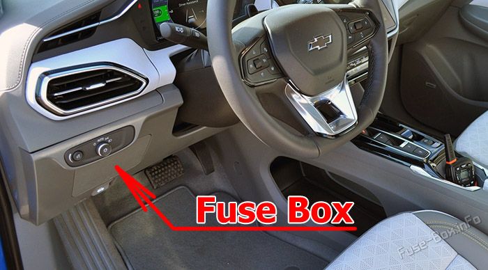
The instrument panel fuse block is on the left side of the instrument panel.
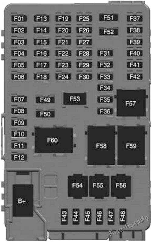
Assignment of the fuses in the instrument panel
Fuse Data
Full access is available to registered users — log in or register.
Log in or register
No. Description F01 Video Processing Module F02 2022: Indicator Light Solar Sensor F03 Side Blind Zone Alert F04 Passive Entry, Passive Start F05 Central Gateway Module F06 Body Control Module 4 F07 Body Control Module 3 F08 Body Control Module 2 F09 Body Control Module 1 F10 Sunroof F11 Amplifier F12 Body Control Module 8 F13 Data Link Connector F14 Parking Assist F15 Headlamp (left) F16 Single Power Inverter Module 1 F17 Body Control Module 6 F18 Body Control Module 5 F19 External Object Calculation Module 2A F20 Advanced Driver Assist Map Module F21 Driver Monitoring System F22 – F23 USB F24 Wireless Charging Module F25 Reflected LED Alert Display F26 Heated Steering Wheel F27 Central Gateway Module 2 F28 Instrument Cluster 2 F29 POLICE_SSV F30 – F31 2022: Telemetics Control Platform (OnStar) F32 – F33 Heating, Ventilation, and Air Conditioning Module F34 HVAC Display/lntegrated Center Stack Display F35 Instrument Cluster 1 F36 Center Stack Module F37 – F38 – F39 – F40 2023: Indicator Light Solar Sensor F41 – F42 – F43 Body Control Module 7 F44 Sensing and Diagnostic Module F45 Front Camera Module F46 Vehicle Integration Control Module F47 Single Power Inverter Module 2 F48 Headlamp (right) F49 Auxiliary Jack F50 Steering Wheel Controls F51 – F52 – F5B Auxiliary Power Outlet F54 – F55 Logistic F56 POLICE_SSV
This content requires JavaScript and a valid membership to view.
Assignment of the relays in the instrument panel
Fuse Data
Full access is available to registered users — log in or register.
Log in or register
No. Description F57 POLICE_SSV F58 Logistics Relay F59 – F60 Accessory / Retained Accessory Power Relay
This content requires JavaScript and a valid membership to view.
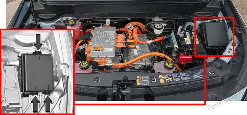
To open the fuse block cover, press the clips at the side and back and pull the cover up.
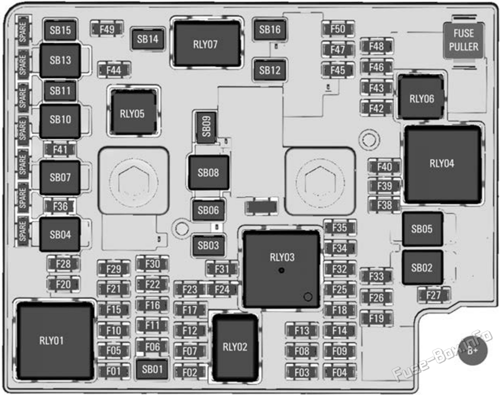
Assignment of the fuses in the under-hood compartment
Fuse Data
Full access is available to registered users — log in or register.
Log in or register
No. Type Description F01 Micro Fuse External Object Calculation Module F02 Micro Fuse Vehicle Integration Control Module F03 Micro Fuse Air Conditioning Compressor Module F04 Micro Fuse Transmission Range Control Module F05 Micro Fuse Power Seat Lumbar F06 Micro Fuse Power Line Communication Module F07 Micro Fuse E-booster F08 Micro Fuse External Object Calculation Module F09 Micro Fuse External Object Calculation Module F10 Micro Fuse Pedestrian Friendly Alert Function F11 Micro Fuse Shifter Interface Board F12 Micro Fuse Shifter Interface Board F13 Micro Fuse Engine Control Module F14 Micro Fuse Single Power Inverter F15 Micro Fuse Voltage, Current, Temperature Module F16 Micro Fuse Power Window Switch / Exterior Rearview Mirror F17 Micro Fuse Interior Rearview Mirror F18 Micro Fuse On-board Charging Module F19 Micro Fuse Auxiliary Heater Pump Motor F20 Micro Fuse Exterior Rearview Mirror F21 Micro Fuse Rain Light Humidity Sensor / Humidity Sensor F22 Micro Fuse Automatic Occupant Sensing F23 Micro Fuse Ventilated Seat F24 Micro Fuse – F25 Micro Fuse HVAC Electric Heater F26 Micro Fuse Engine Control Module F27 Micro Fuse Drive Unit Controller F28 Micro Fuse Rear Window Defogger F29 Micro Fuse E-booster (ECU SRC) F30 Micro Fuse Rechargeable Energy Storage System F31 Micro Fuse – F32 Micro Fuse Power Electronics Coolant Pump F33 Micro Fuse Powertrain Relay F34 Micro Fuse Air Conditioning Compressor Module F35 Micro Fuse Rechargeable Energy Storage System Coolant Pump F36 Micro Fuse – F37 Micro Fuse Headlamp Leveling F38 Micro Fuse Auxiliary Oil Pump F39 Micro Fuse Aeroshutter F40 Micro Fuse Transmission Range Control Module F41 Micro Fuse Rear Wiper F42 Micro Fuse – F43 Micro Fuse – F44 Micro Fuse Liftgate F45 Micro Fuse Horn / Dual Horn F46 Micro Fuse – F47 Micro Fuse Long Range Radar Sensor F48 Micro Fuse – F49 Micro Fuse Rechargeable Energy Storage System 1 F50 Micro Fuse Washer SB01 M-case Fuse Rear Heated Seat SB03 M-case Fuse In-panel Bussed Electrical Center Inline SB06 M-case Fuse Power Window Front SB09 M-case Fuse Power Seat Driver SB11 M-case Fuse In-panel Bussed Electrical Center Power Feed SB12 M-case Fuse Front Wiper SB14 M-case Fuse Front Heated Seat SB15 M-case Fuse Power Window Rear SB16 M-case Fuse – SB02 J-case Fuse Transmission Range Control Module 1 SB04 J-case Fuse E-booster (Motor SRC) SB05 J-case Fuse Electric Cooling Fan SB07 J-case Fuse Electronic Brake Control Module SB08 J-case Fuse – SB10 J-case Fuse Electronic Brake Control Module Power 2 SB13 J-case Fuse Linear Power Module
This content requires JavaScript and a valid membership to view.
Assignment of the relays in the under-hood compartment
Fuse Data
Full access is available to registered users — log in or register.
Log in or register
No. Description RLY01 Rear Window Defogger RLY02 Second Run/Crank RLY03 Run/Crank RLY04 Powertrain RLY05 Liftgate RLY06 – RLY07 Rear Pedestrian Friendly Alert Function
This content requires JavaScript and a valid membership to view.
")