Explore Chevrolet Corvette fuse box diagrams in this focused guide that explains the electrical layout of the latest mid-engine sports car. In this article, we consider the eighth-generation Chevrolet Corvette (Model Code: C8), available from 2020 to 2026 , and provide fuse box diagrams for Chevrolet (Chevy) Corvette 2020, 2021, 2022, 2023, 2024, 2025 and 2026 , along with information about the location of the fuse panels and the assignment of each fuse and relay (fuse layout).
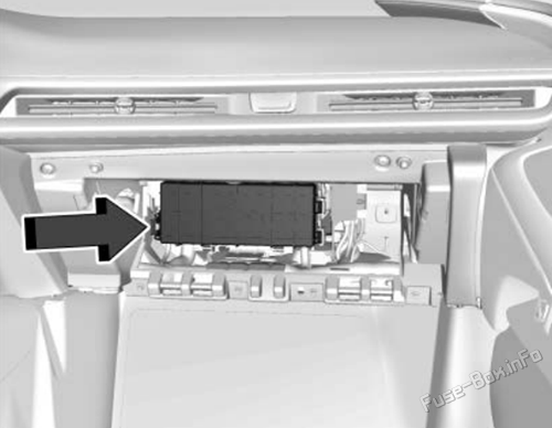
The instrument panel fuse block is behind the glove box. The glove box can be accessed by unlatching the door damper and squeezing the pivot to release the damper ring. Pull the glove box bin side walls in to release the door stops. Then turn the door until the hinge hooks release from hinge pin.
Assignment of the fuses in the Instrument Panel Fuse Box
Fuse Data
Full access is available to registered users — log in or register.
Log in or register
No. Description 1 – 2 Front wiper 3 Cooling fan 1 4 – 5 Cooling fan 2 6 Front blower 7 Front lift/ Automatic level control 8 Shifter interface board module 9 – 10 Display IP cluster/ HVAC/ Center stack module 11 USB 12 – 13 – 14 Glove box 15 – 16 – 17 Remote function actuator 18 Front trunk release 19 Intelligent battery sensor 20 Exterior lighting module 1 21 Exterior lighting module 3 22 Exterior lighting module 4 23 Body control module 2 24 Exterior lighting module 6 25 Amplifier 26 Automatic occupant sensing/ Electric park brake 27 Video processing module 28 Right headlamp 29 – 30 Sensing and diagnostic module/ Automatic occupant sensing 31 Body control module 1 32 Column lock module 33 Data link connection/ Wireless charging module 34 Telematics/Head up display 35 Horn 36 – 37 – 38 Front wash pump 39 Rear auxiliary power outlet 40 Performance data recorder/ Center stack module 41 – 42 Theft deterrent 43 Left headlamp 44 Exterior lighting module 2 45 Power steering column module 46 Body control module 3 47 Exterior lighting module 5 48 Exterior lighting module 7 49 Body control module 4 50 Front auxiliary power outlet 51 – 52 Steering wheel control switch 53 Heated steering wheel 54 –
This content requires JavaScript and a valid membership to view.
Assignment of the relays in the Instrument Panel Fuse Box
Fuse Data
Full access is available to registered users — log in or register.
Log in or register
No. Description K1 – K2 Glove box K3 Horn K4 Front washer K5 Retained accessory power/Accessory K6 Front trunk release 1 K7 – K8 – K9 Front trunk release 2 K10 Wiper
This content requires JavaScript and a valid membership to view.
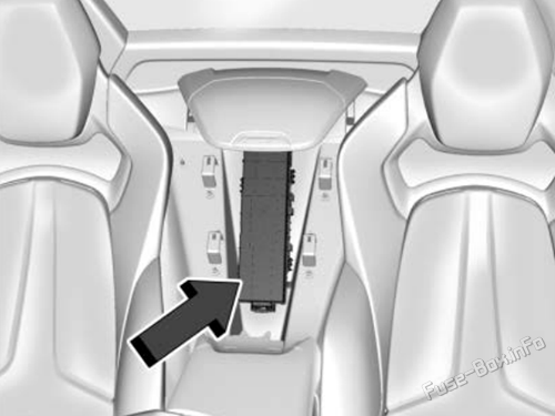
The rear compartment fuse block is in the rear of the vehicle in between the seats.
How to Access:
Open top cover.
Remove the top cover by pushing inward on the latch.
Pull the cover upward.
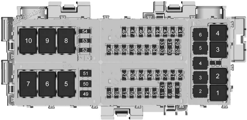
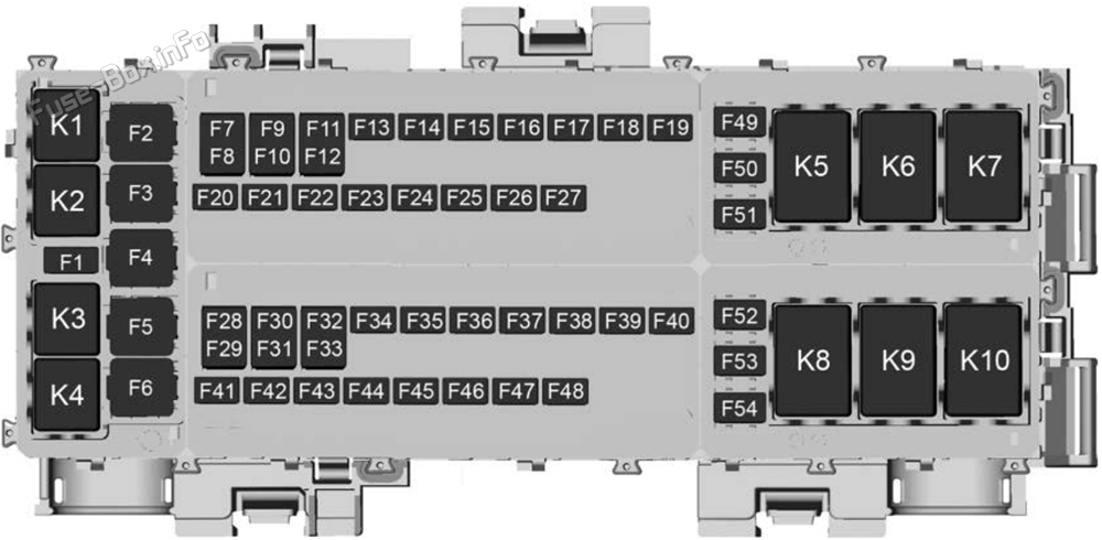
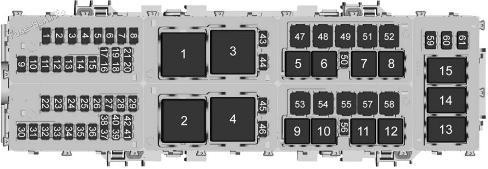
Assignment of the fuses in the Rear Compartment Fuse Box
Fuse Data
Full access is available to registered users — log in or register.
Log in or register
No. Description 1 Driver memory seat module/ Power seat 2 Driver heated seat 3 Passenger memory seat module/ Power seat 4 Passenger heated seat 5 Transmission control module 6 2020: Rear park assist 7 Power sounder module/ Pedestrian friendly alert function 8 Side Blind Zone Alert/ Rear Park Assist 9 Column lock module 10 Engine control module/ Air conditioning 11 – 12 Lithium ion battery module 13 Active fuel management 14 Seat fan 15 – 16 Exterior lighting module 17 Instrument panel cluster/ Shifter interface board/ Transmission control module/ Electronic brake control module 18 Engine control module 19 – 20 Sensing and diagnostic module/ Inside rear view mirror 21 Exhaust valve solenoid 22 Fuel pump/ Fuel tank zone module 23 Tonneau left 24 Tonneau right 25 Convertible top right 26 Convertible top left 27 Electronic suspension control 28 – 29 CGM 30 O2 sensor 31 O2 sensor/ Engine oil/ Canister purge/ Active fuel management 32 Ignition even 33 Ignition odd 34 Engine control module 1 35 Engine control module/ Mass air flow sensor/ O2 sensor/ Air conditioning 36 – 37 Canister vent 38 Latch control module 39 Right window switch/ Door lock 40 Left window switch/ Door lock 41 – 42 Engine control module 2 43 – 44 Air conditioning clutch 45 – 46 – 47 – 48 – 49 Auxiliary cooling fan right 50 – 51 – 52 – 53 Starter solenoid 54 Auxiliary cooling fan left 55 Front lift/Automatic leveling control 56 – 57 Rear window defogger 58 – 59 Left/right window 60 Passenger power seat 61 Driver power seat
This content requires JavaScript and a valid membership to view.
Assignment of the relays in the Rear Compartment Fuse Box
Fuse Data
Full access is available to registered users — log in or register.
Log in or register
No. Description K1 – K2 Powertrain K3 Run/crank K4 Rear defogger K5 Air conditioning clutch K6 – K7 – K8 – K9 – K10 – K11 – K12 – K13 – K14 Starter solenoid K15 –
This content requires JavaScript and a valid membership to view.
")
")
")
")