Explore Chevrolet Tahoe fuse box diagrams in this detailed guide that explains the electrical layout of the third-generation full-size SUV. Here we cover the third-generation Chevrolet Tahoe (Produced from 2005 to 2014) (Model Code: GMT900 ) and provide fuse diagrams for 2007, 2008, 2009, 2010, 2011, 2012, 2013 and 2014 , along with the location of the fuse panels and the assignment of each fuse and relay , giving you a clear reference for electrical diagnostics and maintenance.
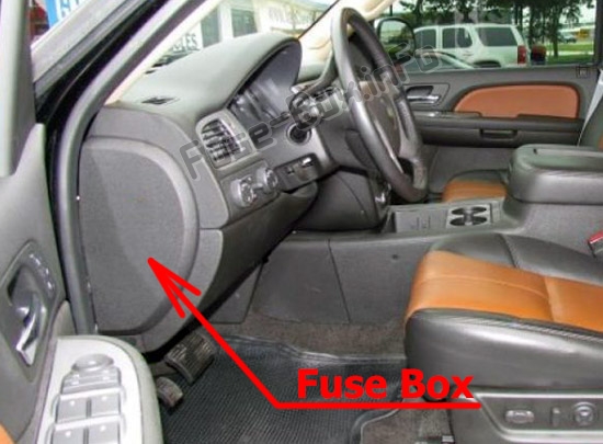
It is located on the driver’s side of the instrument panel, behind the cover.
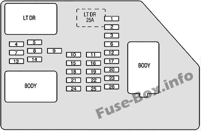
Assignment of the fuses in the Instrument Panel
Fuse Data
Full access is available to registered users — log in or register.
Log in or register
No. Description 1 Rear Seats 2 Rear Accessory Power Outlet 3 Steering Wheel Controls Backlight 4 Driver Door Module 5 Dome Lamps, Driver’s Side Turn Signal 6 Driver’s Side Turn Signal, Stoplamp 7 Instrument Panel Back Lighting 8 Passenger’s Side Turn Signal, Stoplamp 9 2007: Body Control Module 10 Power Door Lock 2 (Unlock Feature) 11 Power Door Lock 2 (Lock Feature) 12 Stoplamps, Center-High Mounted Stoplamp 13 Rear Climate Controls 14 2008-2014: Power Mirror 15 2007: Passenger Door Module, Universal Home Remote System 16 Accessory Power Outlets 17 Interior Lamps 18 Power Door Lock 1 (Unlock Feature) 19 2008-2014: Rear Seat Entertainment 20 Ultrasonic Rear Parking Assist, Power Liftgate 21 Power Door Lock 1 (Lock Feature) 22 2008-2014: Driver Information Center (DIC) 23 Rear Wiper 24 2007: Not used 25 Driver Seat Module, Remote Keyless Entry System 26 Driver Power Done Lock (Unlock Feature)
This content requires JavaScript and a valid membership to view.
Assignment of the Circuit Breakers in the Instrument Panel
Fuse Data
Full access is available to registered users — log in or register.
Log in or register
Short-Code Description LT DR Driver Side Power Window Circuit Breaker
This content requires JavaScript and a valid membership to view.
Assignment of the Harness Connectors in the Instrument Panel
Fuse Data
Full access is available to registered users — log in or register.
Log in or register
Short-Code Description LT DR Driver’s Door Harness Connection BODY Harness Connector BODY Harness Connector
This content requires JavaScript and a valid membership to view.
It is located underneath the instrument panel, to the left of the steering column.
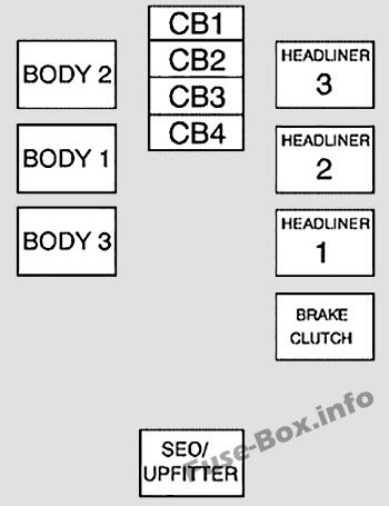
Assignment of the Harness Connectors in the Center instrument panel fuse box
Fuse Data
Full access is available to registered users — log in or register.
Log in or register
Short-Code Description BODY 2 Body Harness Connector 2 BODY 1 Body Harness Connector 1 BODY 3 Body Harness Connector 3 HEADLINER 3 Headliner Harness Connector 3 HEADLINER 2 Headliner Harness Connector 2 HEADLINER 1 Headliner Harness Connector 1 BRAKE CLUTCH Brake Clutch Harness Connector SEO/UPFITTER Special Equipment Option Upfitter Harness Connector
This content requires JavaScript and a valid membership to view.
Assignment of the Circuit Breakers in the Center instrument panel fuse box
Fuse Data
Full access is available to registered users — log in or register.
Log in or register
No. Description CB1 Passenger’s Side Power Window Circuit Breaker CB2 Passenger’s Seat Circuit Breaker CB3 Driver’s Seat Circuit Breaker CB4 Rear Sliding Window
This content requires JavaScript and a valid membership to view.
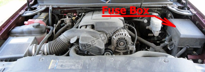
Assignment of the fuses in the Engine Compartment (2007)
Fuse Data
Full access is available to registered users — log in or register.
Log in or register
No. Description 1 Not Used 2 Electronic Stability Suspension Control, Automatic Level Control Exhaust 3 Left Trailer Stop/Turn Lamp 4 Engine Controls 5 Engine Control Module, Throttle Control 6 Right Trailer Stop/Turn Lamp 7 Front Washer 8 Oxygen Sensors 9 Anti-lock Brakes System 2 10 Trailer Back-up Lamps 11 Driver’s Side Low-Beam Headlamp 12 Engine Control Module (Battery) 13 Fuel Injectors, Ignition Coils (Right Side) 14 Transmission Control Module (Battery) 15 Vehicle Back-up Lamps 16 Passenger’s Side Low-Beam Headlamp 17 Air Conditioning Compressor 18 Oxygen Sensors 19 Transmission Controls (Ignition) 20 Fuel Pump 21 Not Used 22 Rear Washer 23 Fuel Injectors, Ignition Coils (Left Side) 24 Trailer Park Lamps 25 Driver’s Side Park Lamps 26 Passenger’s Side Park Lamps 27 Fog Lamps 28 Horn 29 Passenger’s Side High-Beam Headlamp 30 Daytime Running Lamps 31 Driver’s Side High-Beam Headlamp 32 Not Used 33 Sunroof, Emergency Roof Lamp 34 Key Ignition System, Theft Deterrent System 35 Windshield Wiper 36 SEO B2 Upfitter Usage (Battery) 37 Electric Adjustable Pedals 38 Climate Controls (Battery) 39 Airbag System (Ignition) 40 Amplifier 41 Audio System 42 Four-Wheel Drive 43 Miscellaneous (Ignition), Rear Vision Camera, Cruise Control 44 Liftgate Release 45 OnStar®, Rear Seat Entertainment Display 46 Instrument Panel Cluster 47 Not Used 48 Not Used 49 Auxiliary Climate Control (Ignition), Compass-Temperature Mirror 50 Rear Defogger 51 Airbag System (Battery) 52 SEO B1 Upfitter Usage (Battery) 53 Cigarette Lighter, Auxiliary Power Outlet 54 Automatic Level Control Compressor Relay, SEO Upfitter Usage 55 Climate Controls (Ignition) 56 Engine Control Module, Secondary Fuel Pump (Ignition)
This content requires JavaScript and a valid membership to view.
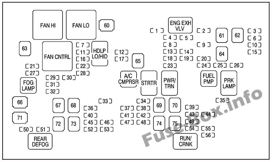
Assignment of the J-Case fuses in the Engine Compartment (2007)
Fuse Data
Full access is available to registered users — log in or register.
Log in or register
No. Description 60 Cooling Fan 1 61 Automatic Level Control Compressor 62 Heavy Duty Anti-lock Brake System 63 Cooling Fan 2 64 Anti-lock Brake System 1 65 Starter 66 Stud 2 (Trailer Brakes) 67 Left Bussed Electrical Center 1 68 Electric Running Boards 69 Heated Windshield Washer System 70 Four-Wheel Drive System 71 Stud 1 (Trailer Connector Battery Power 72 Mid-Bussed Electrical Center 1 73 Climate Control Blower 74 Power Liftgate Module 75 Left Bussed Electrical Center 2
This content requires JavaScript and a valid membership to view.
Assignment of the relays in the Engine Compartment (2007)
Fuse Data
Full access is available to registered users — log in or register.
Log in or register
Short-Code Description FAN HI Cooling Fan High Speed FAN LO Cooling Fan Low Speed ENG EXH VLV Not Used FAN CNTRL Cooling Fan Control HDLP LO/HID Low-Beam Headlamp FOG LAMP Air Conditioning Compressor STRTR Starter PWR/TRN Powertrain FUEL PMP Fuel Pump PRK LAMP Parking Lamps REAR DEFOG Rear Defogger RUN/CRANK Switched Power
This content requires JavaScript and a valid membership to view.
Assignment of the fuses in the Engine Compartment (2008-2014)
Fuse Data
Full access is available to registered users — log in or register.
Log in or register
No. Description 1 Right Trailer Stop/Turn Lamp 2 Electronic Stability Suspension Control, Automatic Level Control Exhaust 3 Left Trailer Stop/Turn Lamp 4 Engine Controls 5 Engine Control Module, Throttle Control 6 Trailer Brake Controller / Right Trailer Stop/Turn Lamp 7 Front Washer 8 Oxygen Sensors 9 Anti-lock Brakes System 2 10 Trailer Back-up Lamps 11 Driver’s Side Low-Beam Headlamp 12 Engine Control Module (Battery) 13 Fuel Injectors, Ignition Coils (Right Side) 14 Transmission Control Module (Battery) 15 Vehicle Back-up Lamps 16 Passenger’s Side Low-Beam Headlamp 17 Air Conditioning Compressor 18 Oxygen Sensors 19 Transmission Controls (Ignition) 20 Fuel Pump 21 Fuel System Control Module 22 Headlamp Washer 23 Rear Windshield Washer 24 Fuel Injectors, Ignition Coils (Left Side) 25 Trailer Park Lamps 26 Driver’s Side Park Lamps 27 Passenger’s Side Park Lamps 28 Fog Lamps 29 Horn 30 Passenger’s Side High-Beam Headlamp 31 Daytime Running Lamps (DRL) ) (If Equipped) 32 Driver’s Side High-Beam Headlamp 33 Daytime Running Lamps 2 (If Equipped) 34 Sunroof 35 Key Ignition System, Theft Deterrent System 36 Windshield Wiper 37 SEO B2 Upfitter Usage (Battery) 38 Electric Adjustable Pedals 39 Climate Controls (Battery) 40 Airbag System (Ignition) 41 Amplifier 42 Audio System 43 Miscellaneous (Ignition), Cruise Control 44 Liftgate Release 45 Airbag System (Battery) 46 Instrument Panel Cluster 47 2008: Power Take-Off 48 2008: Auxiliary Climate Control (Ignition), Compass-Temperature Mirror 49 Center High-Mounted Stoplamp (CHMSL) 50 Rear Defogger 51 Heated Mirrors 52 SEO B1 Upfitter Usage (Battery) 53 Cigarette Lighter, Auxiliary Power Outlet 54 2008: Automatic Level Control Compressor Relay, SEO Upfitter Usage 55 Climate Controls (Ignition) 56 Engine Control Module, Secondary Fuel Pump (Ignition)
This content requires JavaScript and a valid membership to view.
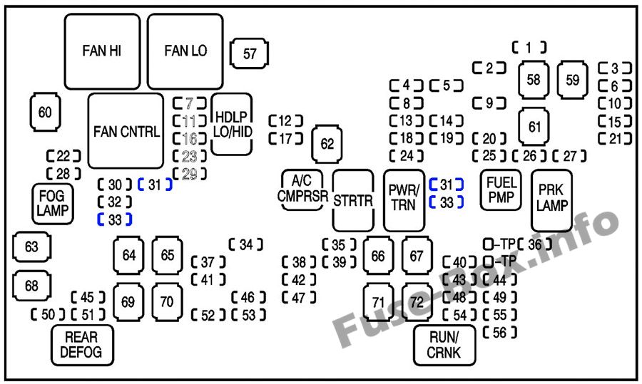
Assignment of the J-Case fuses in the Engine Compartment (2008-2014)
Fuse Data
Full access is available to registered users — log in or register.
Log in or register
No. Description 57 2009-2014: Cooling Fan 1 58 2009-2014: Automatic Level Control Compressor 59 2009-2014: Heavy Duty Antilock Breaking System 60 2008: Cooling Fan 1 61 Antilock Brake System 1 62 Starter 63 Stud 2 (Trailer Brakes) 64 Left Bussed Electrical Center 1 65 Electric Running Boards 66 Heated Windshield Washer System 67 2008: Four-Wheel Drive System 68 Stud 1 (Trailer Connector Battery Power) 69 Mid-Bussed Electrical Center 1 70 Climate Control Blower 71 Power Liftgate Module 72 Left Bussed Electrical Center 2
This content requires JavaScript and a valid membership to view.
Assignment of the relays in the Engine Compartment (2008-2014)
Fuse Data
Full access is available to registered users — log in or register.
Log in or register
Short-Code Description FAN HI Cooling Fan High Speed FAN LO Cooling Fan Low Speed ENG EXH VLV Not Used FAN CNTRL Cooling Fan Control HDLP LO/HID Low-Beam Headlamp FOG LAMP Air Conditioning Compressor STRTR Starter PWR/TRN Powertrain FUEL PMP Fuel Pump PRK LAMP Parking Lamps REAR DEFOG Rear Defogger RUN/CRANK Switched Power
This content requires JavaScript and a valid membership to view.
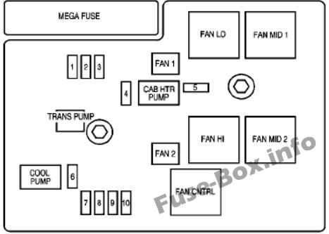
The block is located in the engine compartment near the front of the vehicle.
Assignment of the fuses in the Auxiliary Engine Compartment Fuse Block (Hybrid)
Fuse Data
Full access is available to registered users — log in or register.
Log in or register
No. Description 1 ACPO 2 BECM FAN 3 ACCM 4 CAB HTR PMP 5 EMPTY 6 COOL PUMP 7 EPS 8 Drive Motor/Generator Control Module 1 9 Drive Motor/Generator Control Module 2 10 BECM
This content requires JavaScript and a valid membership to view.
Assignment of the J-Case fuses in the Auxiliary Engine Compartment Fuse Block (Hybrid)
Fuse Data
Full access is available to registered users — log in or register.
Log in or register
Short-Code Description FAN 1 Cooling Fan 1 TRANS PUMP Auxiliary Transmission Fluid Pump FAN 2 Cooling Fan 2 CAB HTR PMP Cab Heater Pump
This content requires JavaScript and a valid membership to view.
Assignment of the relays in the Auxiliary Engine Compartment Fuse Block (Hybrid)
Fuse Data
Full access is available to registered users — log in or register.
Log in or register
Short-Code Desription FAN LOW Cooling Fan Low Speed Relay FAN MID 1 Cooling Fan Mid 1 FAN HI Cooling Fan High Speed Relay FAN MID 2 Cooling Fan Mid 2 FAN CNTRL Cooling Fan Control
This content requires JavaScript and a valid membership to view.
")
")
")
")