The fifth-generation Ford F-Series Super Duty (P708) , designed for heavy-duty performance and durability , has been available from 2023 to the present . Built for towing, hauling, and commercial applications , the F-250, F-350, F-450, and F-550 models offer advanced technology, powerful engine options, and enhanced towing capacity .
In this article, you will find fuse box diagrams for Ford F-250, F-350, F-450, and F-550 models produced between 2023 and 2026 , covering years 2023, 2024, 2025 and 2026 . These diagrams provide essential insights into the fuse layout , helping fleet managers, truck owners, and technicians locate and understand the function of each fuse and relay .
What’s Included:
Fuse Box Diagrams – Clear and detailed visuals to help identify fuses, relays, and circuit breakers .Fuse Panel Locations – Step-by-step guidance on where to find the fuse panels inside the Ford Super Duty trucks.Fuse Assignments – Comprehensive descriptions of the function of each fuse and relay for accurate diagnostics and troubleshooting.
Whether you’re searching for the fuse panel layout , replacing a blown fuse , or diagnosing an electrical issue , this guide is an essential resource. It ensures that your Ford F-Series Super Duty electrical system remains functional and reliable for heavy-duty work and off-road performance .
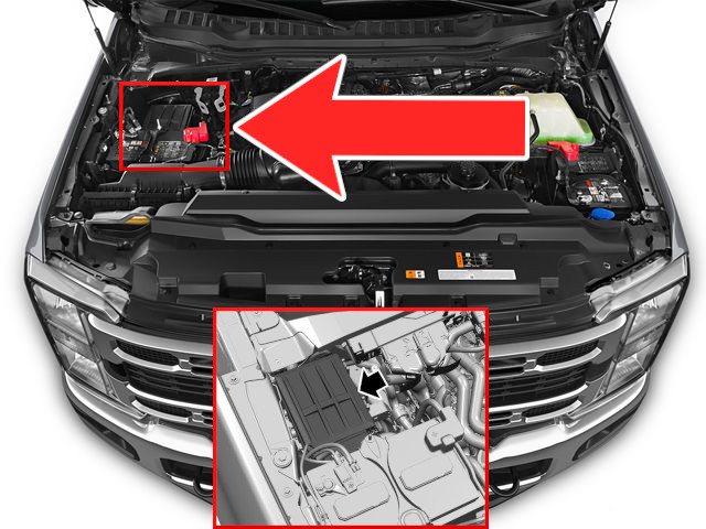
The Ford Super Duty engine compartment fuse box is located on the left side when looking from the front of the vehicle, near the battery.
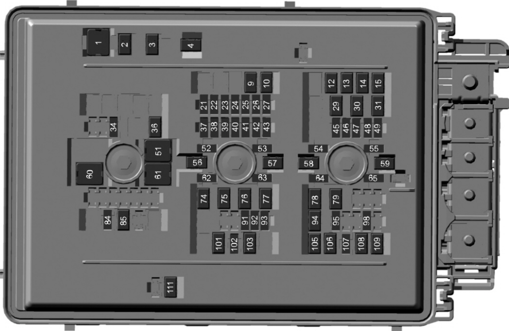
Assignment of the fuses in the engine compartment
Fuse Data
Full access is available to registered users — log in or register.
Log in or register
No. Amp Description 1 50 A Cooling fan 1. 2 50 A Heater. 3 50 A Heater. 4 50 A Heater. 9 30 A Four-wheel drive module. 10 30 A Compressed natural gas module switch. 12 60 A Anti-lock brake system pump. 13 30 A Passenger power seat. 14 40 A Anti-lock brake system valve. 15 30 A Body control module RP2 bus. 21 10 A Trailer tow backup lamps. 22 10 A Four-wheel drive system. 23 20 A Vehicle power 1. 24 20 A Vehicle power 2 (gas). 10 A Vehicle power 2 (diesel). 25 15 A Vehicle power 3 (gas). 10 A Vehicle power 3 (diesel). 26 20 A Vehicle power 4. 27 10 A Vehicle power 5 (gas). 20 A Vehicle power 5 (diesel). 29 15 A Diesel exhaust fluid tank heater. 30 15 A Diesel exhaust fluid line heater. 31 15 A Glow plug and dosing module. 34 20 A Rear heated seats. 36 30 A Climate controlled seat module. 37 5 A 24 V alternator. 38 10 A Powertrain control module. Transmission control module. 39 10 A Anti-lock brake system. 40 10 A Electronic power assist steering. 41 10 A Blind spot information system. Trailer tow tire pressure monitoring system. Rear electronic module controller area network. 42 10 A Snowplow. 43 15 A Interior power distribution box run/start. 45 15 A Heated steering wheel. 46 20 A Not used (spare). 47 5 A Not used (spare). 48 30 A Amplifier. 49 25 A Not used (spare). 51 40 A Blower motor. 52 — Not used. 53 10 A Four-wheel drive – transfer case control module. 54 10 A Not used (spare). 55 10 A Not used (spare). 56 40 A Electronic power assist steering. 57 20 A Trailer tow lighting module. 58 50 A Customer interface module. 59 60 A Inverter. 60 60 A Interior power distribution box B+. 61 30 A Vehicle battery 2. 62 5 A Smart trailer hitch. 63 10 A Smart data link connector. Enhanced central gateway. 64 5 A Glow plug relay coil (diesel). 65 10 A Compressed natural gas module power. 74 30 A Trailer brake control. Aftermarket e-brake access. 75 30 A Compressed natural gas powered at all times. 76 25 A Trailer tow lighting module battery charge. 77 30 A Vehicle battery 1. 78 20 A Power point 2. 79 20 A Power point 1. 84 20 A Horn. 85 40 A Heated rear windshield. 91 5 A Headlamp control module. 92 15 A Left-hand headlamp. 93 15 A Right-hand headlamp. 94 20 A Power point 3. 95 20 A Power point 4. Smart charge module. 98 10 A Tailgate release. 101 50 A Customer interface module. 102 5 A Rain sensor. 103 30 A Front wiper motor. 105 30 A Fuel pump. 106 30 A Body control module RP1 bus. 107 25 A Trailer tow park lamps. 108 40 A Driver power seat. 109 30 A Starter motor. 111 30 A Power sliding rear window.
This content requires JavaScript and a valid membership to view.
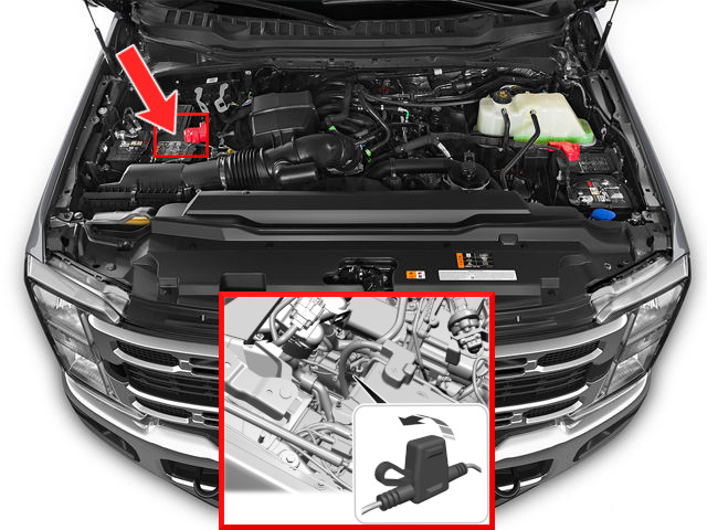
The battery monitoring fuse box is very small and holds only one fuse. It is located on the wire between the battery and the main engine compartment fuse box.
Assignment of the fuse in the engine compartment (Battery Monitoring Fuse Box)
Fuse Data
Full access is available to registered users — log in or register.
Log in or register
No. Amp Protected Description 1 3 A Battery monitoring system.
This content requires JavaScript and a valid membership to view.
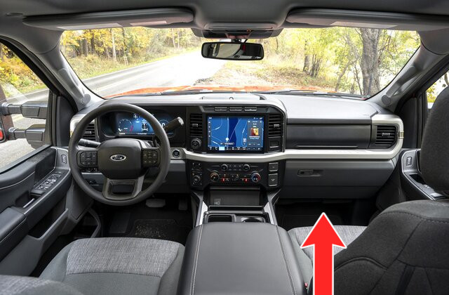
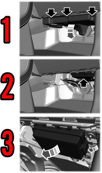
The interior fuse box is located under the glove compartment.
How to Access
Unscrew the three bolts and remove the first lid. Locate the clip on the right side of the second lid, push it down, and remove the lid.
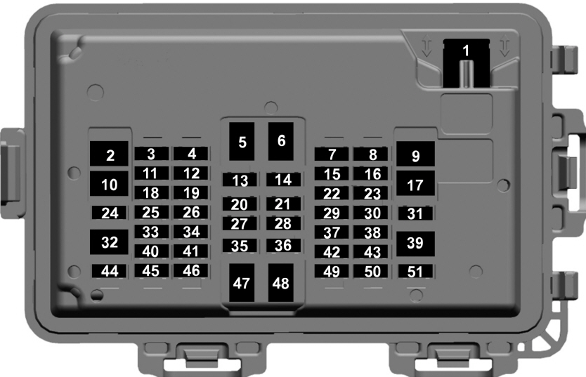
Assignment of the fuses in the passenger compartment
Fuse Data
Full access is available to registered users — log in or register.
Log in or register
No. Amp Description 1 30 A Power windows. 2 30 A Powered tailgate module. 3 30 A Passenger door module. 4 15 A Multi-contour seats. 5 — Not used. 6 — Not used. 7 20 A Advanced driver assistance system module. 8 10 A Delayed accessory logic. 9 — Not used. 10 — Not used. 11 5 A Instrument cluster. 12 — Not used. 13 7.5 A Not used (spare). 14 15 A SYNC. 15 5 A Center high-mounted stop lamp camera. 16 — Not used. 17 — Not used. 18 10 A Radio transceiver module. Four-wheel drive switch. Enhanced central gateway. 19 — Not used. 20 5 A Inverter. 21 5 A Upfitter switch. 22 10 A Auxiliary camera. 23 — Not used. 24 30 A Moonroof. 25 5 A Not used (spare). 26 5 A Not used (spare). 27 5 A Trailer brake control switch. 28 5 A Electrochromatic mirror. 29 5 A Heating, ventilation and air conditioning. 30 — Not used. 31 — Not used. 32 — Not used. 33 10 A Brake on-off switch. 34 7.5 A Steering column control module. Instrument cluster. 35 5 A Rear heated seats. 36 7.5 A Manual shift. Select shift switch. 37 5 A Head up display. 38 7.5 A Telematics control unit. 39 — Not used. 40 10 A Left-hand door switch. Telescopic exterior mirror switch. 41 10 A Adjustable pedals. 42 5 A Central security module. 43 5 A Headlamps. Ignition switch. 44 30 A Driver door module. 45 7.5 A Wireless accessory charger module. Driver front seat module. 46 20 A Radio. 47 — Not used. 48 — Not used. 49 7.5 A SYNC display screen. 50 5 A Auxiliary smart data link connector. 51 — Not used.
This content requires JavaScript and a valid membership to view.
")
")
")
")
")
")