The seventh-generation Ford Falcon (Model Code: FG-X) , following its 2013 facelift , was produced from 2013 to 2016 . As one of the last Australian-built Falcons, this model featured refined styling, updated technology, and strong performance, maintaining its legacy as a durable and spacious sedan.
In this article, you will find fuse box diagrams for Ford Falcon models produced between 2013 and 2016 , covering years 2013, 2014, 2015, and 2016 . These diagrams provide essential insights into the fuse layout , helping owners and technicians locate and understand the function of each fuse and relay.
What’s Included:
Fuse Box Diagrams – Clear and detailed visuals to help identify fuses, relays, and circuit breakers.Fuse Panel Locations – Step-by-step guidance on where to find the fuse panels inside the Ford Falcon.Fuse Assignments – Comprehensive descriptions of the function of each fuse and relay for accurate diagnostics and troubleshooting.
Whether you’re looking for the fuse panel layout , replacing a blown fuse, or diagnosing an electrical issue, this guide is an essential resource. It ensures that your Ford Falcon’s electrical system remains functional and reliable.
Keep your Ford Falcon (2013–2016) running smoothly with this detailed fuse box, fuse panel, and relay guide!
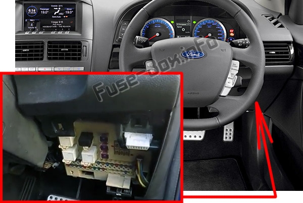
The cigar lighter (power outlet) fuse in the Ford Falcon is fuse №15 , located in the Instrument Panel Fuse Box .
It is located behind the panel on the driver’s side.
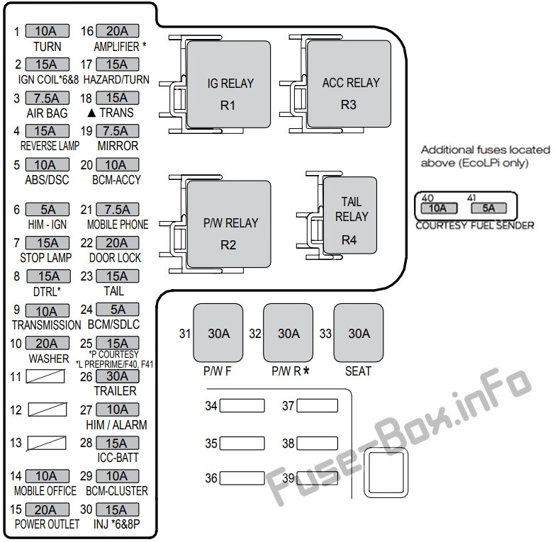
Assignment of the fuses and relays in the Passenger compartment
Fuse Data
Full access is available to registered users — log in or register.
Log in or register
№ Amps Colour Circuits Protected Type 1 10 Red Turn Signal Switch/Memory module (seat) Ignition 2 15 Blue Coil Driver (6 & 8 cylinder) Ignition 3 7.5 Brown Airbag Ignition 4 15 Blue Reverse Lights, Park Aid Ignition 5 10 Red DSC / ABS Ignition 6 5 Tan HIM Ignition 7 15 Blue Stop Lights, (PCM) Ignition 8 15 Blue Daytime Running Lights Ignition 9 10 Red Transmission Ignition 10 20 Yellow Washer Pump Accessory 11 – – Not Used – 12 – – Not Used – 13 – – Not Used – 14 10 Red Mobile Phone Accessory 15 20 Yellow Power Outlet Accessory 16 20 Yellow Amplifier Battery 17 15 Blue Turn Signal / Hazard Lights Battery 18 15 Blue Transmission (I4) Battery 19 7.5 Brown Power Mirrors, Rear Demister Relay, Electrochromatic Mirror Accessory 20 10 Red Body Control Module Accessory 21 7.5 Brown Mobile Phone Battery 22 20 Yellow Door Locks Battery 23 15 Blue Tail/Park Lights, Switch Illumination, Display, Cluster, Interior Command Centre Battery -Tail Relay 24 5 Tan Body Control Module/SDLC Battery 25 15 Blue Petrol: Interior Lights, Solar Sensor, Gearshift (sports sequential), Rain Sensor Battery/ Battery Saver 26 30 Green Trailer Battery 27 10 Red HIM, Alarm, Diagnostic connector Battery 28 15 Blue Interior Command Centre, Display Battery 29 10 Red Instrument Cluster, Body Control Module Ignition 30 15 Blue Injectors (petrol) (6 & 8 cylinder) Ignition 31 30 Pink Front Power Windows Battery, BCM Switched Window Relay 32 30 Pink Rear Power Windows 33 30 Pink Power Seats Battery 34 – – Not Used – 35 – – Not Used – 36 – – Not Used – 37 – – Not Used – 38 – – Not Used – 39 – – Not Used – Additional Fuses – Located Above the Instrument Panel Fuse Box (EcoLPi only) 40 10 Red Interior Lights, Solar Sensor, Gearshift (sports sequential) – EcoLPi, Rain Sensor Battery/ Battery Saver 41 5 Tan Fuel Tank Level Sensor – EcoLPi Battery/ Battery Saver Relays R1 – White Ignition Ignition R2 – White Power Windows BCM Switched R3 – White Accessory Accessory R4 – Black Tail Lights Light Switch
This content requires JavaScript and a valid membership to view.
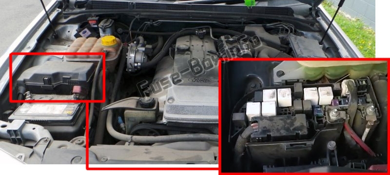
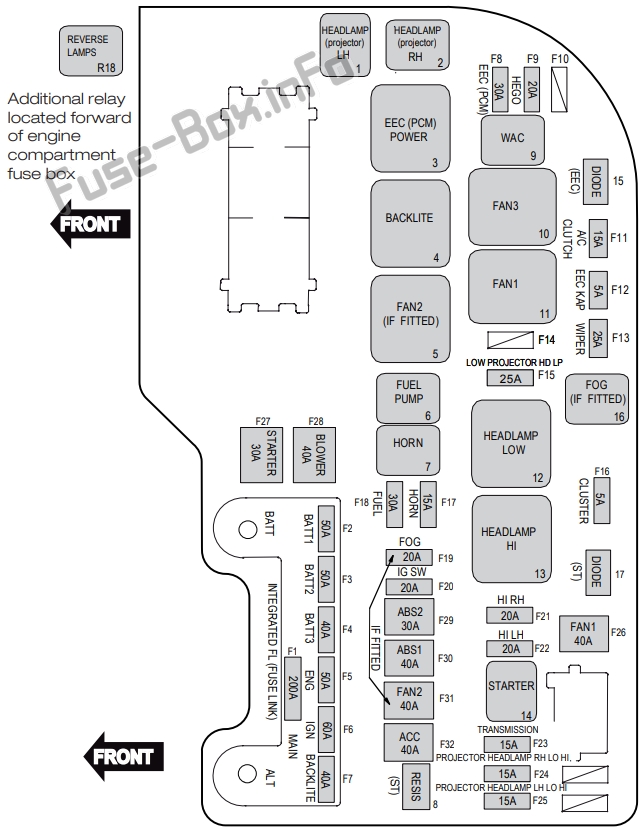
Assignment of the fuses and relays in the Engine compartment (6 Cylinder Petrol)
Fuse Data
Full access is available to registered users — log in or register.
Log in or register
№ Amps Colour Circuits Protected F1 200 Black – intergrated fuse link Main F2 50 Black – intergrated fuse link Batt 1 F3 50 Black – intergrated fuse link Batt 2 F4 40 Black – intergrated fuse link Batt 3 F5 50 Black – intergrated fuse link Eng F6 60 Black – intergrated fuse link Ignition F7 40 Black – intergrated fuse link Backlight (Demister) F8 30 Green EEC (PCM), IMCC, VCT F9 20 Yellow Hego F10 – – Not Used F11 15 Blue Air Conditioning Compressor F12 5 Tan EEC (PCM) KAP F13 25 Natural Wiper Front F14 – – – F15 25 Natural Headlamps – Projector Lamps (Low) F16 5 Tan Cluster F17 15 Blue Horn F18 30 Green Fuel F19 20 Yellow Fog Lamp F20 20 Yellow Ignition Switch, Alternator, Relay Coil, Fan, Ignition, Accessory F21 20 Yellow Headlamp – High – Right F22 20 Yellow Headlamp – High – Left F23 15 Blue Transmission (Battery) F24 15 Blue Headlamp – Low/High-Projector-RH F25 15 Blue Headlamp – Low/High-Projector-LH F26 40 Green Fan 1 F27 30 Pink Starter F28 40 Green Blower Fan – Climate Control F29 30 Pink ABS 2 DSC2 (DSC VR) F30 40 Green ABS1 DSC1 (DSC MR) F31 40 Green Fan 2 F32 40 Green Accessory Relays 1 Black Headlamp (Projector) – Keep on with High (LH) 2 Black Headlamp (Projector) – Keep on with High (RH) 3 White EEC (PCM) 4 White Backlight (Demister) 5 Green Fan 2 6 Black Fuel 7 Black Horn 9 Black WAC (Air-Conditioning Compressor) 10 White Fan 3 11 White Fan 1 12 White Headlamp (Low) 13 White Headlamp (High) 14 Black Starter 16 Black Fog R18 Black Reverse Lamps (6-Speed Automatic Transmission) Diode 15 Black EEC (PCM) 17 Black Starter Resistor 8 Green Starter
This content requires JavaScript and a valid membership to view.
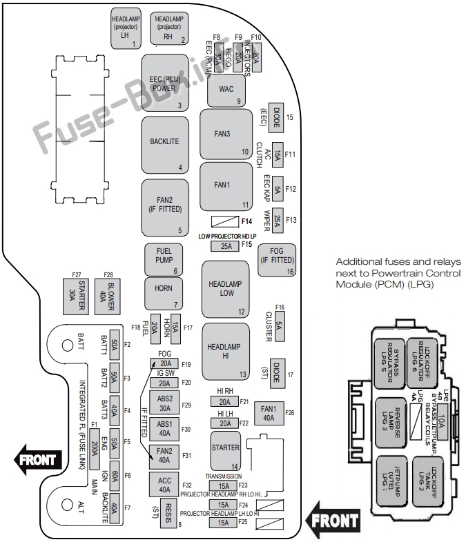
Assignment of the fuses and relays in the Engine compartment (EcoLPi)
Fuse Data
Full access is available to registered users — log in or register.
Log in or register
№ Amps Colour Circuits Protected F1 200 Black – integrated fuse link Main F2 50 Black – integrated fuse link Batt 1 F3 50 Black – integrated fuse link Batt 2 F4 40 Black – integrated fuse link Batt 3 F5 50 Black – integrated fuse link Eng F6 60 Black – integrated fuse link Ignition F7 40 Black – integrated fuse link Backlight (Demister) F8 30 Green EEC (PCM), LPG Relay Coils, LPG Bypass and Jet Pump Relay Feed, IMCC, VCT F9 20 Yellow Hego F10 20 Yellow Injector, LPG Module (LPG Engine) F11 15 Blue Air-Conditioning Compressor F12 5 Tan EEC (PCM) and LPG module KAP F13 25 Natural Wiper Front F14 – – – F15 25 Natural Headlamps – Projector Lamps (Low) F16 5 Tan Cluster F17 15 Blue Horn F18 20 Yellow Fuel (LPG) F19 20 Yellow Fog Lamp F20 20 Yellow Ignition Switch, Alternator, Relay Coil, Fan, Ignition, Accessory F21 20 Yellow Headlamp – High – Right F22 20 Yellow Headlamp – High – Left F23 15 Blue Transmission (Battery) F24 15 Blue Headlamp – Low/High – Projector-RH F25 15 Blue Headlamp – Low/High – Projector-LH F26 40 Green Fan 1 F27 30 Pink Starter F28 40 Green Blower Fan – Climate Control F29 30 Pink ABS 2 DSC2 (DSC VR) F30 40 Green ABS1 DSC1 (DSC MR) F31 40 Green Fan 2 F32 40 Green Accessory Relays 1 – Black Headlamp (Projector) – Keep on with High (LH) 2 – Black Headlamp (Projector) – Keep on with High (RH) 3 – White EEC (PCM) (LPG Engine) 4 – White Backlight (Demister) 5 – Green Fan 2 6 – Black Fuel 7 – Black Horn 9 – Black WAC (Air-Conditioning Compressor) 10 – White Fan 3 11 – White Fan 1 12 – White Headlamp (Low) 13 – White Headlamp (High) 14 – Black Starter 16 – Black Fog Diode 15 – Black EEC (PCM) 17 – Black Starter Resistor 8 – Green Starter Additional Fuses and Relays Located Beside the Powertrain Control Module (PCM) in the Engine Compartment LPG1 – Black Fuel Tank Jet Pump Solenoid (Ute Only) LPG2 – Black Fuel Tank Lock Off Solenoid LPG3 – Black Reverse Lamps LPG 4A – – Not Used LPG 4B 10 Red Relay Coils (Lockoff, Bypass and Jet Pump) Solenoids – Bypass and Jet Pump (LPG engine) LPG5 – Black Regulator Bypass Solenoid LPG6 – Black Regulator Lock Off Solenoid
This content requires JavaScript and a valid membership to view.
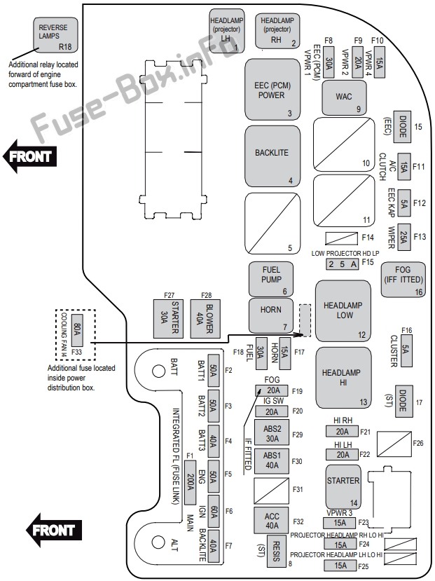
Assignment of the fuses and relays in the Engine compartment (EcoBoost I4)
Fuse Data
Full access is available to registered users — log in or register.
Log in or register
№ Amps Colour Circuits Protected F1 200 Black – integrated fuse link Main F2 50 Black – integrated fuse link Batt 1 F3 50 Black – integrated fuse link Batt 2 F4 40 Black – integrated fuse link Batt 3 F5 50 Black – integrated fuse link Eng F6 60 Black – integrated fuse link Ignition F7 40 Black – integrated fuse link Backlight (Demister) F8 30 Green VPWR 1 (ECM,EEC) Relay Coil (WAC and Fuel Pump) F9 20 Yellow VPWR 2, HEGO, UEGO, Cannister Purge, Tl VCT (Intake and Exhaust) F10 15 Blue VPWR 4 F11 15 Blue Air-Conditioning Compressor F12 5 Tan EEC (ECM) KAP F13 25 Natural Wiper Front F14 – – – F15 25 Natural Headlamps – Projector Lamps (Low) F16 5 Tan Cluster F17 15 Blue Horn F18 30 Green Fuel F19 20 Yellow Fog Lamp (if equipped) F20 20 Yellow Ignition Switch, Alternator, Relay Coil, Fan, Ignition, Accessory F21 20 Yellow Headlamp – High – Right F22 20 Yellow Headlamp – High – Left F23 15 Blue VPWR 3 – VRVS, ECBV (Vacuum Regulator Valve Solenoid, Electronic Compressor Bypass Valve) F24 15 Blue Headlamp – Low/High – Projector-RH F25 15 Blue Headlamp – Low/High – Projector-LH F26 – – Not Used F27 30 Pink Starter F28 40 Green Blower Fan – Climate Control F29 30 Pink ABS 2 DSC2 (DSC VR) F30 40 Green ABS1 DSC1 (DSC MR) F31 – – Not Used F32 40 Green Accessory F33 80 – Engine Cooling Fan (Midi Fuse) Relay 1 – Black Headlamp (Projector) – Keep on with High (LH) 2 – Black Headlamp (Projector) – Keep on with High (RH) 3 – White EEC (ECM/PCM) 4 – White Backlight (Demister) 5 – – Not Used 6 – Black Fuel 7 – Black Horn 9 – Black WAC (Air-Conditioning Compressor) 10 – – Not Used 11 – – Not Used 12 – White Headlamp (Low) 13 – White Headlamp (High) 14 – Black Starter 16 – Black Fog R18 – Black Reverse Lamps (6-speed Automatic Transmission) Diode 15 – Black EEC (ECM/PCM) 17 – Black Starter Resistor 8 – Green Starter
This content requires JavaScript and a valid membership to view.
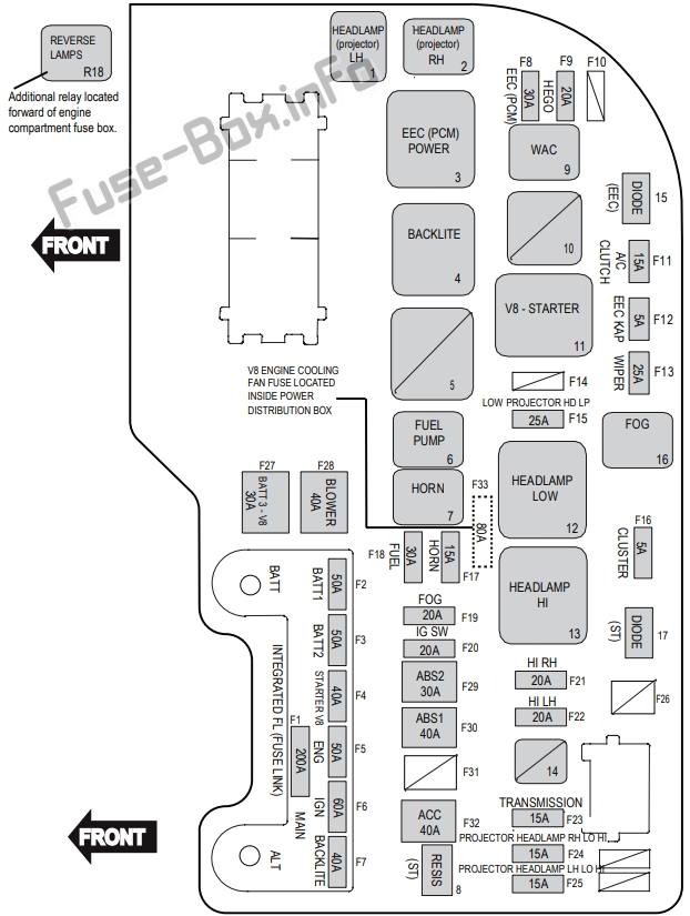
Assignment of the fuses and relays in the Engine compartment (V8)
Fuse Data
Full access is available to registered users — log in or register.
Log in or register
№ Amps Colour Circuits Protected F1 200 Black – intergrated fuse link Main F2 50 Black – intergrated fuse link Batt 1 F3 50 Black – intergrated fuse link Batt 2 F4 40 Black – intergrated fuse link Starter V8 Engine F5 50 Black – intergrated fuse link Eng F6 60 Black – intergrated fuse link Ignition F7 40 Black – intergrated fuse link Backlight (Demister) F8 30 Green EEC (PCM), IMCC, VCT F9 20 Yellow Hego F10 – – Not Used F11 15 Blue Air Conditioning Compressor F12 5 Tan EEC (PCM) KAP F13 25 Natural Wiper Front F14 – – Not Used F15 25 Natural Headlamps – Projector Lamps (Low) F16 5 Tan Cluster F17 15 Blue Horn F18 30 Green Fuel F19 20 Yellow Fog Lamp F20 20 Yellow Ignition Switch, Alternator, Relay Coil, Fan, Ignition, Accessory F21 20 Yellow Headlamp – High – Right F22 20 Yellow Headlamp – High – Left F23 15 Blue Transmission (Battery) F24 15 Blue Headlamp – Low/High-Projector-RH F25 15 Blue Headlamp – Low/High-Projector-LH F26 – – – F27 30 Pink Batt 3 V8 Engine F28 40 Green Blower Fan – Climate Control F29 30 Pink ABS 2 DSC2 (DSC VR) F30 40 Green ABS 1 DSC1 (DSC MR) F31 – – – F32 40 Green Accessory F33 80 – Engine Cooling Fan V8 Engine Relays 1 – Black Headlamp (Projector) – Keep on with High (LH) 2 – Black Headlamp (Projector) – Keep on with High (RH) 3 – White EEC (PCM) 4 – White Backlight (Demister) 5 – – – 6 – Black Fuel 7 – Black Horn 9 – Black WAC (Air-Conditioning Compressor) 10 – – – 11 – White Starter V8 Engine 12 – White Headlamp (Low) 13 – White Headlamp (High) 14 – – – 16 – Black Fog R18 – Black Reverse Lamps (6-Speed Automatic Transmission). Diode 15 – Black EEC (PCM) 17 – Black Starter Resistor 8 – Green Starter
This content requires JavaScript and a valid membership to view.
")