The Ford Ranger , a dependable midsize pickup truck, has been celebrated for its rugged performance and versatility. Covering models from 2011 to 2018 , this guide is designed to assist owners and technicians in maintaining and troubleshooting the vehicle’s electrical systems.
In this article, you will find fuse box diagrams for Ford Ranger models produced between 2011 and 2018 , including years 2011, 2012, 2013, 2014, 2015, 2016, 2017, and 2018 . These diagrams provide essential information about the fuse layout and relay assignments.
What’s Included:
Fuse Box Diagrams : Clear and detailed visuals for quick identification of fuses and relays.Fuse Panel Locations : Step-by-step guidance on locating the fuse panels inside your Ford Ranger.Fuse Assignments : Comprehensive explanations of each fuse and relay’s function for diagnostics and repairs.
Whether you are addressing an electrical issue, replacing a fuse, or performing regular maintenance, this guide is an indispensable resource for Ford Ranger owners and technicians. It ensures that your vehicle’s electrical systems remain functional and reliable.
Maintain the reliability and performance of your Ford Ranger (2011–2018) with this detailed fuse box guide!
The cigar lighter (power outlet) fuses in the Ford Ranger are:
Fuse №20 : Cigar LighterFuse №24 : Auxiliary Power Socket (Front Console)Fuse №31 : Auxiliary Power Socket (Rear Console)Fuse №46 : Auxiliary Power Socket (Floor Console)
All are located in the Engine Compartment Fuse Box .
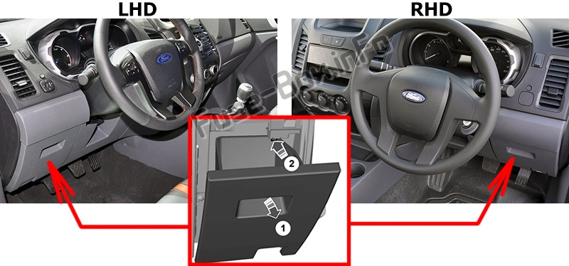
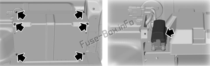
It is located behind the cover on the instrument panel.
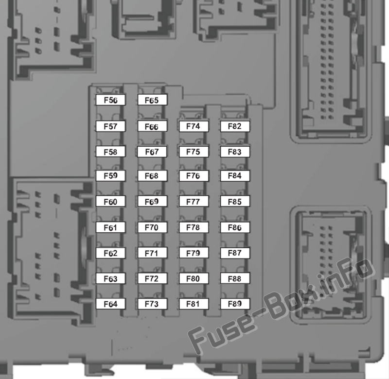
Assignment of the fuses in the Passenger compartment
Fuse Data
Full access is available to registered users — log in or register.
Log in or register
№ Ampere rating Circuits protected 56 20 Fuel pump 57 – Not used 58 – Not used 59 5 Passive anti-theft system (PATS) 60 10 Interior lamp, driver’s door switch pack, mood lights, puddle lights, Automatic shifter, footwell lamp 61 – Not used 62 5 Rain sensor module 63 5 Tachograph / Not used 64 – Not used 65 – Not used 66 20 Driver’s door lock, central double locking 67 5 Stop lamp switch 68 – Not used 69 5 Instrument cluster, Integrated control module (ICP), Tracking and blocking module 70 20 Central locking 71 5 Air conditioning 72 7.5 Alarm horn 73 5 On-board diagnostics II 74 20 Main beam 75 15 Front fog lamps 76 10 Reversing lamp, rear view mirror 77 20 Washer pump 78 5 Ignition switch 79 15 Radio, multi-function display 80 20 Multi-function display, Hi audio, brake valve closing (BVC) module 81 5 Interior motion sensor 82 20 Washer pump ground 83 20 Central locking ground 84 20 Driver’s door unlock, central double locking ground 85 7.5 Instrument cluster, parking aid module, rear view camera, manual air conditioning, rear view mirror, tracking and blocking module 86 10 Restraint system, passenger air-bag deactivation indicator 87 5 Tachograph 88 – Not used 89 – Not used
This content requires JavaScript and a valid membership to view.
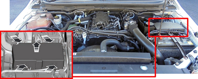
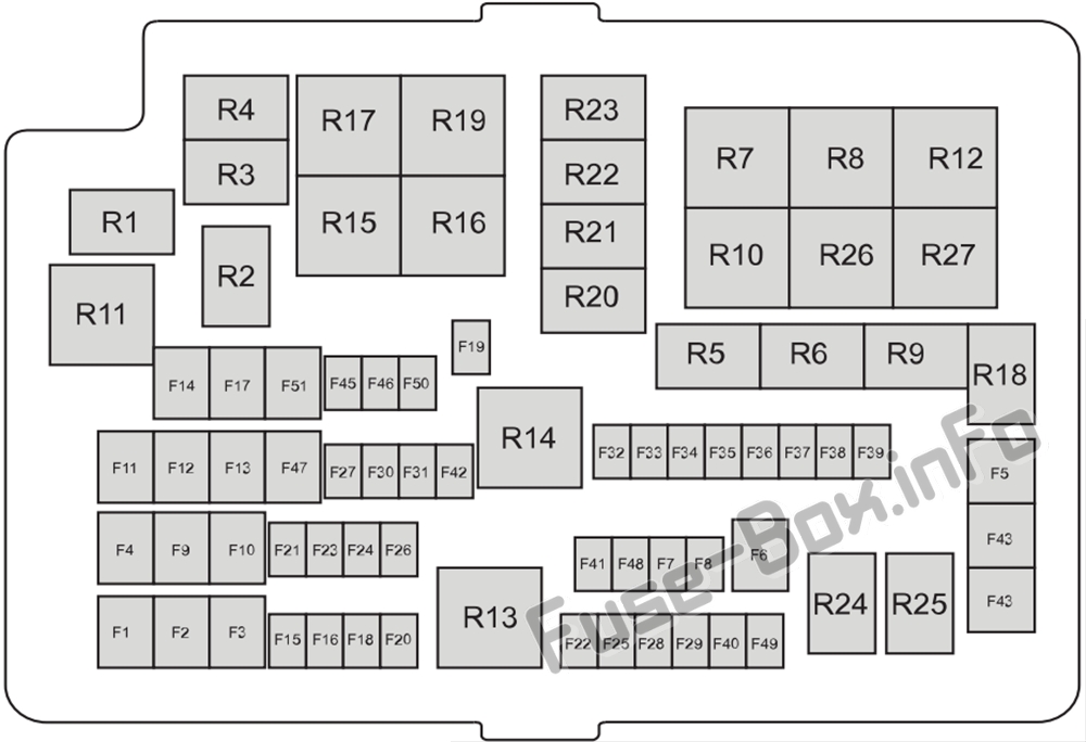
Assignment of the fuses and relays in the engine compartment
Fuse Data
Full access is available to registered users — log in or register.
Log in or register
№ Ampere rating Circuits protected 1 60 Passenger compartment fuse box supply (battery) 2 60 Passenger compartment fuse box supply (battery) 3 (Petrol) 50 Engine cooling fan 3 (Diesel) 60 Glow plug control module 4 40 ABS module 5 30 Electric windows (front and rear) 6 25 Four wheel drive (4WD) motor ground 7 – Not used 8 – Not used 9 20 Electric seat 10 25 Electric windows (front) 11 30 Blower motor 12 25 Four wheel drive (4WD) motor power 13 20 Starter solenoid 14 20 Heated rear window 15 (Petrol) 10 Flex-fuel pump 15 (Diesel) 15 Vapouriser glow plug 16 10 Air conditioning Clutch 17 25 Power windows (front) 18 25 Windscreen wiper motor 19 25 Wndscreen wiper motor ground 20 20 Cigar lighter 21 15 Horn 22 15 Fuel injectors or flex-fuel valve 23 10 Differential lock solenoid 24 20 Auxiliary power socket (front console) 25 15 Ignition coils, Temperature and Mass Air Flow sensor, Glow plug module, Vacuum Control Valve (VCV), Electronic Vacuum Regulator Valve (EVRV) 26 7.5 Electronic control module (ECM) 27 10 Transmission control module (TCM) 28 10 Heated exhaust gas oxygen, Universal Heated Exhaust Gas Oxygen-sensor, Relay coils 29 15 Electronic control module (ECM) 30 15 Battery monitoring sensor 31 20 Auxiliary power socket (rear console) 32 5 A/C pressure switch 33 10 Transmission control module (TCM) 34 5 PTC heater (where fitted) / Crew chief module / Spare 35 20 Passenger compartment fuse box supply (Ignition) 36 5 ABS module 37 10 Headlamp levelling 38 20 Heated seat 39 10 Power mirrors 40 10 Vapouriser pump / Not used 41 10 Heated mirrors 42 10 Alarm horn 43 30 Heated windscreen (right) 44 30 Heated windscreen (left) 45 25 ABS module 46 20 Auxiliary power socket (floor console) 47 40 Trailer tow module 48 – Not used 49 – Not used 50 5 Ignition relay, Relay coils 51 (Brazil only) 30 Electric windows (rear) 51 20 Trailer tow (12 or 13 pin battery feed, Permanent live) Relays R1 Key interlock R2 Wiper on or off R3 Horn R4 A/C clutch R5 Differential lock R6 Wper Hi or Lo R7 Engine cooling fan low R8 Engine cooling fan high R9 Flex-fuel pump, Vapouriser glow plug R10 Heated rear window R11 Heated windscreen R12 Not used R13 Electronic control module (ECM) power hold R14 Ignition R15 4WD motor 2 (Clockwise) R16 4WD motor 1 (Counter clockwise) R17 4WD motor R18 Security horn R19 Starter motor R20 Not used R21 Not used R22 Not used R23 Not used R24 Not used R25 Not used R26 Blower motor R27 Electric seat
This content requires JavaScript and a valid membership to view.
Release the catches and remove the cover.
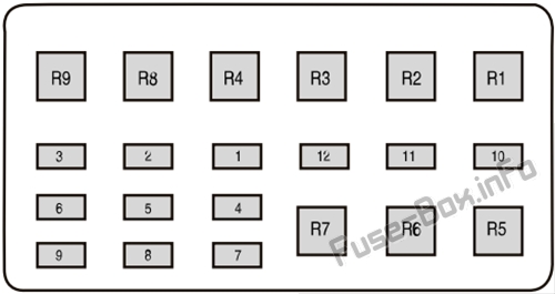
Assignment of the fuses and relays in the Auxiliary fuse box
Fuse Data
Full access is available to registered users — log in or register.
Log in or register
№ Amp Rating Protected Components 1 25 Driving Light 2 15 Position lamp 3 10 LED beacon 4 15 Work lights 5 20 Spare 6 20 Power point 7 15 Reversing lamp 8 15 Direction indicators, stop lamp 9 5 Crew chief 10 5 Disable fuse (isolator ground) 11 – Not used 12 – Not used Relays R1 Work lights R2 LED beacon R3 Spare R4 Position lamp R5 Direction indicator (left) R6 Direction indicator (right) R7 Stop lamp R8 Not used R9 Not used
This content requires JavaScript and a valid membership to view.


")