")
")

The first-generation Mercedes-Benz A-Class (W168), produced from 1996 to 2004, was a revolutionary model that introduced the brand to the compact car segment. With its innovative “sandwich floor” design, it offered enhanced safety and space efficiency in a small footprint. Despite its compact size, the W168 provided surprising versatility, advanced engineering, and the premium feel expected from Mercedes-Benz.
In this article, you will find fuse box diagrams for the Mercedes-Benz A-Class, covering models A140, A160, A170, A190, and A210 for the years 1996 through 2004. These diagrams offer essential insight into the vehicle’s fuse layout, enabling owners and technicians to identify and understand the function of each fuse and relay.
What’s Included:
- Fuse Box Diagrams – Detailed, easy-to-read illustrations identifying fuses, relays, and their corresponding systems.
- Fuse Panel Locations – Guidance on where the fuse panels are located within the A-Class, including interior and engine compartment positions.
- Fuse Assignments – Comprehensive descriptions of what each fuse and relay controls, aiding accurate electrical diagnostics and repairs.
Whether you’re replacing a faulty fuse, diagnosing an electrical issue, or simply performing preventative maintenance, this guide helps ensure the reliability and safety of your Mercedes-Benz A-Class (W168).
Keep your first-generation A-Class running at its best with this complete fuse box, fuse panel, and relay guide tailored for model years 1996–2004.
- The cigar lighter (power outlet) fuse in the Mercedes-Benz A-Class is located in the Passenger Compartment Fuse Box:
- fuse №12 (Cigarette Lighter, 12V Socket in Trunk)
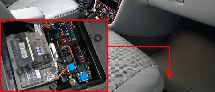
Passenger Compartment Fuse Box
Fuse box location
The fuse box is located under the floor near the passenger seat (remove the floor panel, cover, and soundproofing).
Fuse box diagram
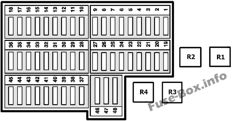
Assignment of the fuses and relay in the passenger compartment
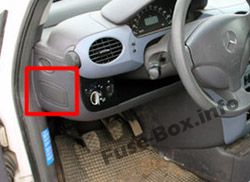
Light Control Fuses (in the instrument panel)
Fuse box location
They are located in the side of the instrument panel on the driver’s side.
Fuse box diagram
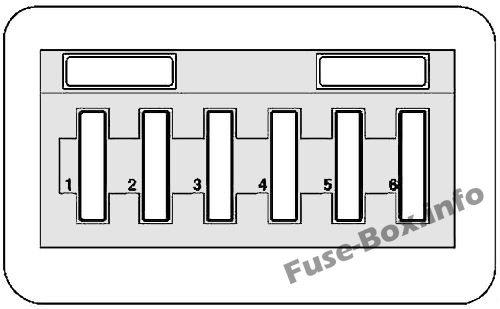
Light Control Fuses
Engine Compartment Relay Box
Fuse box location
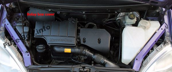
Fuse box diagram
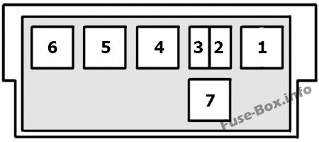
Engine Compartment Relay Box