Mercedes-Benz Sprinter Fuse Box Diagram and Location (2006-2018)
The second-generation Mercedes-Benz Sprinter (W906, NCV3), produced from 2006 to 2018, is a versatile and reliable commercial van used for cargo transport, passenger shuttles, and specialized utility applications. With its efficient diesel engines, spacious interior, and advanced safety features, the W906 remains a popular choice for businesses, fleet operators, and van life enthusiasts.
In this article, you will find fuse box diagrams for Mercedes-Benz Sprinter models produced between 2006 and 2018, covering years 2006, 2007, 2008, 2009, 2010, 2011, 2012, 2013, 2014, 2015, 2016, 2017, and 2018. These diagrams provide crucial insights into the fuse layout, helping vehicle owners, mechanics, and technicians locate and understand the function of each fuse and relay.
What’s Included:
Fuse Box Diagrams – Clear and detailed visuals to help identify fuses, relays, and circuit breakers.
Fuse Panel Locations – Step-by-step guidance on where to find the fuse panels inside the Mercedes-Benz Sprinter.
Fuse Assignments – Comprehensive descriptions of each fuse and relay function for accurate diagnostics and troubleshooting.
Whether you’re searching for the fuse panel layout, replacing a blown fuse, or diagnosing an electrical issue, this guide is an essential resource. It ensures that your Mercedes-Benz Sprinter’s electrical system remains functional and reliable for commercial deliveries, passenger transport, and camper van conversions.
Keep your Mercedes-Benz Sprinter (2006–2018) running efficiently with this detailed fuse box, fuse panel, and relay guide!
The cigar lighter (power outlet) fuses in the Mercedes-Benz Sprinter are:
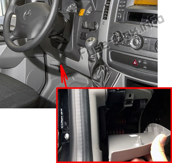
Instrument Panel Fuse Box:
Fuse №13: Cigarette Lighter, PND (Personal Navigation Device) Power Socket
Fuse №25: 12V Socket – Center Console
Fuse Box under Driver’s Seat:
Fuse №23: 12V Left Rear Socket (Load/Rear Compartment)
Fuse №24: 12V Socket under the Base of Driver’s Seat
Fuse №25: 12V Right Rear Socket (Load/Rear Compartment)
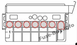
Auxiliary heating, digital timer/rear view camera/neutral gate switch, starting-off aid and allwheel drive/engine runon/DIN slot basic wiring (roof)/FleetBoard/anti-theft protection with vehicle tracking/emergency hammer lighting in the rear compartment
5
4
Tachograph/ADR working speed governor/ power take-off/AAG (trailer control unit)
7.5
5
ECO Start/control unit EGS (electronic gearbox control)
5 10
6
All-wheel drive control unit Auxiliary oil pump
5 10
7
ESM (electronic selector module)
10
8
Loading tailgate/tipper vehicle PARKTRONIC (Vehicles with code XM0)
10
9
Rear compartment air conditioning, compressor clutch, disengagea-ble reverse warning device
7.5
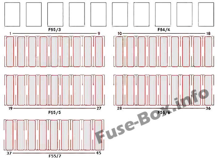
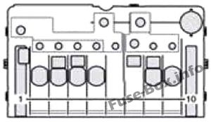
Fuse block F55/4
10
Terminal 30, body/ equipment manufacturer
25
11
Terminal 15, body/ equipment manufacturer
15
12
D+, body/equipment manufacturer
10
13
Fuel pump FSCM (Fuel Sensing Control Module) Fuel pump relay (Vehicles with code MI6/MH3/XM0) (NAFTA)
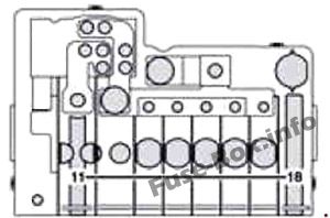
Overhead control panel without ATA (Anti-Theft Alarm system) and without rain sensor Overhead control panel with ATA (Anti-Theft Alarm system) Overhead control panel with rain sensor
Terminal 30, body electrics (courier vehicles) Rear window defroster without ATA (Anti-Theft Alarm system) Rear window defroster with ATA (Anti-Theft Alarm system)
SRB starter relay (fuse and relay module) (NAFTA) (Vehicles with code XM0) Starterfor electrical supply support using the additional battery
25
29
Terminal 87 (7), gas system, vehicles with a natural gas engine (NGT) (Natural Gas Technology) Selective Catalytic Reduction control unit, vehicles with exhaust gas aftertreatment (NAFTA) Terminal 30, all-wheel drive, control unit
7.5 10 30
30
Auxiliary heat exchanger fan Brake booster (NAFTA)
15 30
31
Rear compartment heating blower Sliding door closing assistance, left Electric sliding door, left
30 15 30
32
Selective Catalytic Reduction relay supply, vehicles with exhaust gas aftertreatment KEYLESS ENTRY
5 10
33
Electric sliding door, right Sliding door closing assistance, right ENR (level control) control unit Compressor air suspension
30 15 30 30
34
Selective Catalytic Reduction heater 3 DEF (Diesel Exhaust Fluid) supply reservoir, vehicles with exhaust gas aftertreatment, 6 cyl. Diesel (Vehicles with code MH3) (NAFTA) Selective Catalytic Reduction heater 1 DEF, vehicles with exhaust gas aftertreatment diesel (Not for vehicles with code MH3)
15 20
35
Selective Catalytic Reduction heater 2 hose, vehicles with exhaust gas aftertreatment, 6 cyl. Diesel (Vehicles with code MH3) (NAFTA) Selective Catalytic Reduction heater 2 DEF, vehicles with exhaust gas aftertreatment diesel (Not for vehicles with code MH3)
15 25
36
Selective Catalytic Reduction heater 1 delivery pump, vehicles with exhaust gas aftertreatment, 6 cyl. Diesel (Vehicles with code MH3) (NAFTA) Selective Catalytic Reduction heater control 3 DEF, vehicles with exhaust gas aftertreatment diesel (Not for vehicles with code MH3)
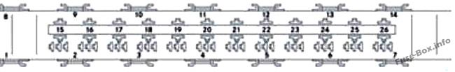
Preglow relay Secondary air pump for vehicles with a gasoline engine
80 40
2
Air-conditioning system coolingfan – cab without partition and without rear-compartment air-conditioning system Air-conditioning system cooling fan – cab with partition and reinforced without rear-compartment air-conditioning system Air-conditioning system cooling fan – cab/ Electrical suction fan Starter relay, terminal 15 (Vehicles with code XM0) Starter relay unsupported (Vehicles with code XM0)
60 40 40 25 25
3
SAM (signal acquisition and actuation module)/SRB (fuse and relay module)
80
4
Auxiliary battery/ retarder Rear-compartment air-conditioning system
150 80
5
Terminal 30 pre-fuse boxes, SAM (signal acquisition and actuation module)/SRB (fuse and relay module) Terminal 30 electrical heater booster (PTC) input (Vehicles with code XM0)
150 Bridge
6
Connection point on the base of the seat Pre-fuse box in the base of the seat (Vehicles with code XM0)
Bridge Bridge
7
Rear-compartment air-conditioning system Electrical heater booster PTC
80 150
Pre-fuse box at the base of the driver’s seat (only for auxiliary battery) F59/7
Pre-fuse box at the base of the driver’s seat (only for auxiliary battery) F59/7
Fuse Data
Full access is available to registered users — log in or register.
Electrical heater booster (PTC) Rear-compartment air-conditioning system
150 80
14
Air-conditioning system coolingfan – cab without partition and without rear-compartment air-conditioning system Air-conditioning system cooling fan – cab with partition and reinforced without rear-compartment air-conditioning system Air-conditioning system cooling fan – cab open vehicle model designation Electrical suction fan
60 40 40 70
15
Unassigned
16
Retarder not in combination with battery cutoff relay Battery cutoff relay
100 150
17
Unassigned
–
18
Alternator
300
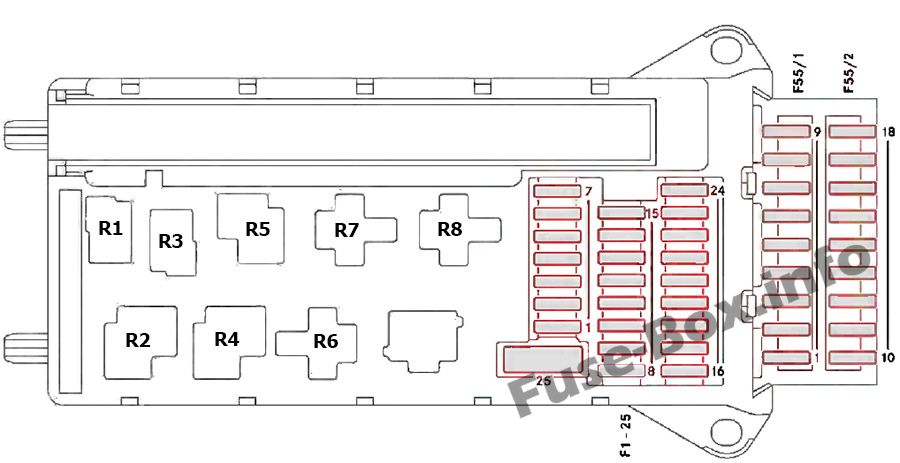
Relays
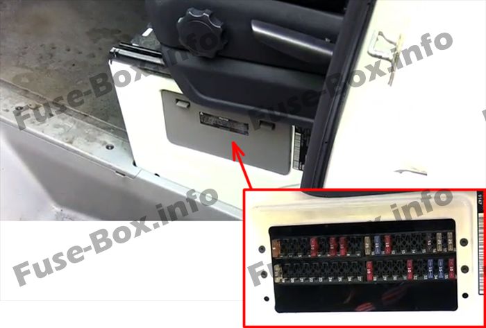
Fuse Box Location
Under the driver’s side seat
Fuse Box Diagram
Relays in the seat base of the left front seat
Fuse Data
Full access is available to registered users — log in or register.